Assessment Tools
Assign | Assess | Analyse
Quick Quiz
Objective Assessment
Question Bank
List Of Questions With Key, Aswers & Solutions
Back To Learn
Re – Learn
Go Back To Learn Again
Chapter Level Content
Assign | Assess | Analyse
Objective Assessment
List Of Questions With Key, Aswers & Solutions
Back To Learn
Go Back To Learn Again
Mind Map Overal Idea Content Speed Notes Quick Coverage What havewe discussed? A fraction is a number representing a partof a whole. The whole maybe a single object or agroup of objects. (Scroll down till end of the page) Study Tools Audio, Visual & Digital Content Whenexpressing a situation of counting partsto write a fraction, readmore
Overal Idea
Content
Quick Coverage
What havewe discussed? A fraction is a number representing a partof a whole. The whole maybe a single object or agroup of objects. (Scroll down till end of the page)
Audio, Visual & Digital Content
Whenexpressing a situation of counting partsto write a fraction, itmust be ensured that allparts are equal.
In5/7, 5 iscalled the numerator and 7 iscalled the denominator.
Fractions can beshown on a number line.
Every fraction has a point associated with it onthe number line.
In a proper fraction, the numerator is less than the denominator.
Thefractions, where the numerator is greater than the denominator are called improper fractions.
An improper fraction can be written as a combination of a whole and a part, and such fraction then called mixed fractions.
Each proper or improper fraction has many equivalent fractions.
To find an equivalent fraction of a given fraction, we may multiply or divide boththe numerator andthe denominator ofthe given fraction by the samenumber.
A fraction issaid to bein the simplest (or lowest) formif its numerator and the denominator haveno common factor except 1.
Topic Terminology
Term
Table:
.
Test Your Learning

Assign | Assess | Analyse
Objective Assessment
List Of Questions With Key, Aswers & Solutions
Back To Learn
Go Back To Learn Again
Mind Map Overal Idea Content Speed Notes Quick Coverage Content Study Tools Speed Notes Notes For Quick Recap Study Tools Audio, Visual & Digital Content The Right Mentor Educational Services Mr. Amarnath Reddy Email: info@therightmentor.com www.therightmentor.com CBSE 10 PHYSICS Light – Reflection And Refraction _____________________________________________ Full Notes Introduction To Reflection and Refraction of Light Light readmore
Overal Idea
Content
Quick Coverage
Content
Notes For Quick Recap
Audio, Visual & Digital Content
The Right Mentor
Educational Services
Mr. Amarnath Reddy
Email: info@therightmentor.com
CBSE 10 PHYSICS
Light – Reflection And Refraction
_____________________________________________
Introduction To Reflection and Refraction of Light
Light travels in a straight path in a uniform medium.
The light that bounces back when it strikes a smooth or rough Opaque surface is called reflection of light.
Light bends when it travels from one transparent medium to the other transparent medium at the surface that separates the two transparent media. Such a phenomenon is called Refraction of light.
Reflection of light
Reflection of light is of two types they are;
(i) Specular or Regular
(ii) Diffused or Irregular Reflection.
(i) Specular or Regular


In the case of reflection, The light obeys two laws of reflection as follows.
(i) angle of incidence, i is equal to the angle of reflection, r. Mathematically, it is represented as: ∠i = ∠r
(ii) The incident ray, The normal ray and reflected ray lie in the same plane.
The image formed by a mirror, such as a plane mirror and a spherical mirror are due to regular reflection of light.
Based on the nature of images formed by the mirrors, the images are of two types they are:
Real images are the images which can be captured onto a screen.The real images are formed when the light rays really meet at a point.
Example, Slide projector in a cinema hall forms an image on the screen.
Virtual images are the images which cannot be caught on a screen.
The virtual images are formed when the light ranys really do not meet at a point.
But they appear to be images formed by the meeting of light rays.
Note:
For example, the images formed due to reflection of light by a plane mirror of a dressing table and parking (convex) mirror.
Types of Mirrors
Generally the mirrors are classified into the following two types as:
Generally mirrors refer to plane mirrors. But if the surface of a mirror is curved it is said to be a curved mirror.
Examples:
Concave mirror, convex mirror and Elliptical mirror etc.,
If the curvature of a mirror is a huge sphere, the mirror is said to be a spherical mirror.
Examples:
Concave mirror, convex mirror
Spherical mirrors are a special type of curved mirror.
Characteristics of Image Formed By A Plane Mirror
*The image formed by a plane mirror is unmagnified, virtual and erect.
*The image formed by a plane mirror has right-left reversal known as lateral Inversion.
*Focal length of a plane mirror is infinite.
*Power of a plane mirror is zero.
*If a plane mirror is turned by an angle, θ , the reflected ray turns by 2θ .
*The least size of a plane mirror to view an object is equal to half the size of the object.
Curved – Mirrors
A mirror that has a curved reflecting surface is said to be a curved mirror.
Spherical Mirrors

If the curvature of a mirror is a huge sphere, the curved mirror is said to be a spherical mirror.
The reflecting surface of a mirror can be curved inwards or curved outwards.
Curved mirrors and Spherical mirrors are classified into the following two types:
A curved mirror or a spherical mirror whose reflecting surface is curved inward is known as a concave mirror.
Conversely, A curved mirror or a spherical mirror whose reflecting surface is outward curved is known as a convex mirror.


*Pole – The geometric centre of the reflecting surface of a spherical mirror is its pole. It is represented by P.
*Centre of curvature – The centre of the curvature of the reflecting surface of a spherical mirror is known as centre of curvature. It is represented by C.
*Centre of curvature in a convex mirror lies behind the mirror.
*But it lies in front of the mirror in a concave mirror.
*Radius of curvature – The radius of the reflecting surface of the spherical mirror is known as radius of curvature. It is represented by R.
*Principal axis – Straight line passing through the pole and centre of curvature in a spherical mirror is known as principal axis.
*Principal focus – The reflected rays appear to come from a point on the principal axis, known as principal focus. Principal focus (F) is the point on the principal axis, where a parallel beam of light, parallel to the principal axis after reflection converges in the case of a concave mirror and appears to diverge from in the case of a convex mirror.
*Focal length – The distance between the pole and the principal focus in a spherical mirror, known as focal length and it is represented by f.
*Note: Radius of curvature is twice the focal length (R=2f). In other words, The focal length is half the radius of curvature.
*Focal plane: A plane, drawn perpendicular to the principal axis such as it passes through the principal focus is called the focal plane.
*Aperture – The diameter of the reflecting surface is known as its aperture. The size of the mirror is called its aperture. In other words It is also defined as the effective diameter of the light reflecting area of the mirror.
Image Formation by Spherical Mirrors

Rule 1: An incident light ray parallel to the principal axis, passes through the principal focus or appears to pass through the principal focus after reflection.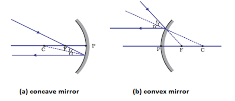
Rule 2: An incident light ray that passes through the principal focus or appears to pass through the principal focus, travel parallel to the principal axis after reflection.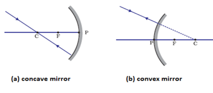
Rule 3: An incident light ray that passes through the center of curvature or appears to pass through the center of curvature, after reflection and retraces its initial path.
Rule 4: A ray incident obliquely to the principal axis towards the pole, P of the curved mirror (concave mirror and convex mirror) is reflected obliquely.
Note:
The incident and reflected rays always follow the laws of reflection at the point of incidence (P) making equal angles with the principal axis.
that passes through the center of curvature or appears to pass through the center of curvature, after reflection and retraces its initial path.
Reflection By Concave Mirrors
| Incident Ray | Reflected Ray |
| Parallel to principal axis | Passes through focus |
| Passes through C | Retraces its path |
| Passes through focus | parallel to principal axis |
| Strikes the pole at an angle with principal axis | Makes the same angle with the principal axis. |
Reflection by Convex Mirror
| Incident Ray | Reflected Ray |
| Parallel to principal axis | Appears to pass through focus |
| Directed towards the focus | Appears to pass parallel to principal axis |
| Strikes the pole at an angle with principal axis | Makes the same angle with principal axis |
Concave Mirror
A spherical mirror whose reflecting surface is curved inward is known as a concave mirror.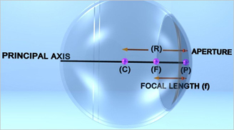
Terms Associated With Concave Mirror
The geometric centre of a concave mirror is called its pole.
The centre of the sphere from which the concave mirror was cut is called the centre of curvature of the concave mirror.
The centre of curvature of the reflecting surface of a concave mirror is called the centre of curvature of the concave mirror.
The distance from any point on the concave mirror to its center of curvature is called the radius of curvature of the concave mirror.
An imaginary line passing through the center of curvature and the pole of the concave mirror is called the principal axis of the concave mirror.
The area of a concave mirror that is exposed to incident light is called the aperture of the concave mirror.
The length along the principal axis from the pole to the principal focus is called the focal length of the concave mirror.
If an object is placed close to a concave mirror such that the distance between the mirror and the object is less than its focal length, then a magnified and virtual image is formed.
This property of the concave mirror is used in many applications such as a dentist mirror to view the inner parts of the mouth clearly and a shaving mirror.
Concave mirrors converge the light incident on them and hence are called converging mirrors.
Image Formation by Concave Mirror
Location of an image of an object formed by a concave mirror by drawing the ray diagrams.
*We can locate the image of an object formed by a concave mirror by drawing the ray diagrams.
*The intersecting point of at least two reflections will give the position of image of the point object.
*The following rays can be used to draw the ray diagrams.
*A ray parallel to the principal axis of a concave mirror.
*A ray passing through the focus of the concave mirror
*A ray which is passing through the centre of curvature of a concave mirror
*A ray incident obliquely to the principal axis on a concave mirror.
Rules for Drawing Ray Diagrams in Spherical Concave Mirrors
A ray parallel to the principal axis of a concave mirror.
*A ray parallel to the principal axis of the concave mirror reflects through its focus.
A ray passing through the focus of the concave mirror.
*A ray passing through the focus of the concave mirror reflects parallel to the principal axis.
A ray which is passing through the centre of curvature of a concave mirror
*A ray which is passing through the centre of curvature of a concave mirror reflects back on the same path.
*A ray incident obliquely to the principal axis on a concave mirror.

A ray when incident obliquely to the principal axis on a concave mirror also reflects obliquely.
Concave Mirrors – Ray Diagrams
Depending on the position of the object in front of the concave mirror, the position, size and the nature of the image varies.
Object at infinity

A real, inverted, highly diminished image is formed at the focus, F, in front of the concave mirror.
Object beyond C
A real, inverted, diminished image is formed between C and F, in front of the concave mirror.
Object at C
A real, inverted, same sized image is formed at C, in front of the concave mirror.
Object between C and F
A real, inverted, enlarged image is formed beyond C, in front of the concave mirror.
Object at F
A real, inverted, highly enlarged image is formed at infinity, in front of the concave mirror.
Object between F and P
A virtual, erect and enlarged image is formed behind the concave mirror.
Image Formation by a Concave Mirror
| Object Location | Image Location | Nature of Image | |
| Infinity | At F | Real, InvertedHighly DiminishedMagnification<<1 | |
| Beyond C | Beyond F and C | Real, InvertedDiminishedMagnification<1 | |
| At C | At C | Real, InvertedEqual to size of objectMagnification=1 | |
| Between C and F | Beyond C | Real, InvertedMagnifiedMagnification>1 | |
| At F | Infinity | Real, InvertedHighly MagnifiedMagnification>>1 | |
| Between F and P | Behind the mirror | Virtual, ErectMagnifiedMagnification>1 | |
Convex Mirror
A spherical mirror whose reflecting surface is curved outward is known as a convex mirror.
Terms Associated With Convex Mirror
The geometric centre of the curvature of the convex mirror is called its pole.
The centre of curvature of the reflecting surface of a convex mirror is called the centre of curvature of the convex mirror.
The distance from any point on the reflecting surface of a convex mirror to its centre of curvature is called radius of curvature of the convex mirror.
An imaginary line passing through the centre of curvature and the pole of the convex mirror is called the principal axis of the convex mirror.
The reflected rays, when projected backwards, appear to meet at a point on the principal axis. This point is called the principal focus. The length along the principal axis from the pole to the principal focus is called the focal length of the concave mirror.
The area of a convex mirror that is exposed to incident light is called the aperture of the convex mirror.
If the aperture of a convex mirror is small, then Convex mirrors, such as the rear view mirrors of cars and bikes, always form erect, virtual, and diminished images.
The location of the object does not affect the characteristics of the image formed by a convex mirror.
When an object approaches a convex mirror, the image formed by the mirror also approaches the mirror, but not proportionately. Because of this it is mentioned as “Objects seen in the mirror are closer than they appear” on the outside rear view mirrors of vehicles.
Image Formation by Concave Mirror
ray diagrams –
The two rays that can be used to draw the ray diagram are:
Reflection by Convex Mirror
| Incident Ray | Reflected Ray |
| Parallel to principal axis | Appears to pass through focus |
| Directed towards the focus | Appears to pass parallel to principal axis |
| Strikes the pole at an angle with principal axis | Makes the same angle with principal axis |
Image Formed By A Convex Mirror
Irrespective of the position of the object, a virtual, erect and diminished image is formed between F and P, behind the convex mirror.

Convex mirrors are used as:
Sign Convention for Spherical Mirrors

Table Showing Sign Convention
| Type of Mirror | Object Distance, u | Image Distance, v | Focal length, f | Radius of Curvature, R | Height of the Object, hO | Height of the Image, hi | ||
| Real | Virtual | Real | Virtual | |||||
| Concave mirror | –Ve | –Ve | +Ve | –Ve | –Ve | +Ve | –Ve | +Ve |
| Convex mirror | –Ve | Virtual image | +Ve | +Ve | +Ve | +Ve | Virtual image | +Ve |
The relation between the focal length (f), object distance (u) and the image distance (v) is given by:

The ratio of the height of the image in a spherical mirror, to the height of the object is called magnification (m)
Magnification,m = Height of Image, HHeight of Object, i= Image Distance, HObject Distance, i
The distance from the principal focus to the pole of the mirror is the focal length of the mirror and is equal to half the radius of curvature, which is the distance between the centre of curvature and the pole.
For a real image object distance (u) and the image distance (v) are negative and the magnification is negative.
If the magnification of an image is negative it does mean that the image is real and inverted.
On the other hand for a virtual image object distance (u) is negative and image distance (v) is positive and hence the magnification is positive, i.e., the image is erect.
If the magnification of an image is positive it does mean that the image is virtual and erect.
Convex mirrors diverge the light incident on them and hence they are called the diverging mirrors.
Due to this they always form diminished, virtual and erect images irrespective of the position of the object in front of them.
Thus, the magnification caused by these mirrors is always less than one.
The field of view for a convex mirror is greater than that for a plane mirror, the aperture being the same.
Hence, convex mirrors are used as rear-view mirrors in vehicles.
It is also installed behind automated teller machines as a security measure.
The field of view for a convex mirror is greater than that for a plane mirror, the aperture being the same.
Hence, convex mirrors are used as rear-view mirrors in vehicles. It is also installed behind automated teller machines as a security measure.
The images formed by convex mirrors are always diminished, virtual and erect, irrespective of the position of the object.
| Convex Mirror | Concave Mirror |
| Convex mirror is curved outwards. | 1. Concave mirror is curved inwards. |
| The focal point of the convex mirror is behind the mirror. | 2. The focal point of the concave mirror is in front of the mirror. |
| In convex mirrors the image is always virtual, upright and smaller than the object. | 3. In the case of concave mirrors different types of images are formed on different locations of the object. The image is upside down (inverted) and far away but if we bring the object close to the mirror then the image will be larger and upright. |
| Convex mirrors are used in cars (as passenger-side mirrors since they provide upright and wide view), they are also used in camera phones, for safety measures there are also used in roads and driveways.Besides these convex mirrors are found in many hospitals, schools etc. as hallway safety mirrors. | 4. Concave mirrors are used in telescopes. These are also used as make up and shaving mirrors since these provide larger images. Besides these concave mirrors are used by dentists and also used in headlights of cars, solar devices, satellite dishes etc. |
Light bends while traveling from one medium to another. Since the refraction of light occurs at the surface joining two media, the refraction is a surface phenomenon.
The bending of light when it travels from one medium into another is called refraction of light.
The reason for refraction of light is the change in speed of light.
The speed of light in an optically rarer medium is more than that in an optically denser medium.

Mathematically, (sin i)/(sin r)= (n2/n1) (Or)
(sin i)/(sin r)= (1n2), where (1n2), is the refractive index of the medium 2, in which the refracted ray travels, with respect to medium 1, in which the incident ray travels.
This law is credited to Willebrord Snell and is, therefore, called Snell’s law.
If wng is the refractive index of glass w.r.t. water, ang be the refractive index of glass w.r.t. air and anw be the refractive index of water w.r.t. air ,then
wng= ang/anw
The extent to which a light ray bends depends on the refrangibility of the ray with respect to the medium.
The ratio of velocity of light in vacuum to that in a medium is termed as the absolute refractive index (m) of the medium. Absolute refractive index (m) of the medium is the measure of the ability of light to get bent in the given medium.
Measuring the speed of light is difficult.
We can determine the refractive index using Snell’s law
According to Snell’s law,![]()
Refraction of Light At A plane Surface
The bottom of a water glass appears to rise upwards when viewed normally. This is due to the vertical shift of the bottom of the glass, which takes place because of refraction.
Refraction of Light At Glass Slab
When a light ray, incident at an angle, passes through a glass slab, the emergent ray shifts laterally, known as lateral shift.
The lateral shift depends on the thickness and refractive index of the glass slab.
If the angle of incidence increases gradually, the angle of refraction also increases.
But, at a particular angle of incidence in the denser medium, the refracted ray emerges along the surface. That particular angle is known as the critical angle.
If the angle of incidence is greater than the critical angle, the ray undergoes Total Internal Reflection.
The formation of Mirages in deserts is due to total internal reflection of light.
n=cv
n=(Speed of light in vacuum)/( speed of light in the medium)
As light travels from one medium to another, the frequency of light does not change.

Lenses
A lens is a piece of transparent optical material with one or two curved surfaces to refract light rays.
The simplest lens has two spherical surfaces close enough together that we can neglect the distance between them. Such a lens is called a thin lens.
The two common types of lenses are Converging lens or Convex lens.
It should be noted that, if the above lenses are surrounded by a material with a refractive index greater than that of the lens, the convex lens gets converted into a concave lens and vice versa.
A lens may converge or diverge light rays to form an image.
A bi-convex lens is one with a surface that is bulged outwards on both the sides. It is generally referred to as a convex lens.
Another type of lens is a bi-concave lens that has two inward bent surfaces. It is generally referred to as a concave lens.
A Plano-convex lens has a convex surface on one side and a plane surface on the other.
A Plano-concave lens is the one that has a concave surface on one side and a plane surface on the other.
A concavo-convex lens has a concave surface on one side and a convex surface on the other.
Convex and concave lenses are important as they are more commonly used than the other types of lenses.
Terms Used for Lens
Center of Curvature: The center of the imaginary glass sphere of which the lens is a part, is called center of curvature.
Principal Axis: An imaginary line joining the centers of curvature of the two spheres, of which lens is a part, is called Principal Axis.
Optic Center: A point within the lens, where a line drawn through the diameter of lens meets the principal axis, is called the optic center.
Principal Focus for Convex Lens: It is a point on the principal axis of a convex lens, where parallel beams of light rays, traveling parallel to the principal axis, after passing through the lens actually meet.
Principal Focus for Concave Lens: It is a point on the principal axis of a concave lens, from where a parallel beam of light rays, traveling parallel to the principal axis, after passing through the lens, appears to come.
Focal Length: The distance between principal focus and optical centre is called focal length.
Aperture: The effective diameter of the lens through which refraction takes place is called aperture of lens.
Optic centre is a point on the axis of a lens such that any light ray passing through this point emerges without refraction.
• Principal focus is a point on the axis of a lens.
A lens in which both the surfaces are convex, is known as convex lens.
Since the convex lens converges the light incident on it. It is called the converging lens.
The convex lenses form different types of images depending on its relative position with respect to the position of the object in front of them.
A lens in which both the surfaces are concave, is known as a concave lens.
Since the concave lens diverges the light incident on it. It is called the diverging lens.
Due to this the concave lenses always form diminished, virtual and erect images irrespective of the position of the object in front of them.
Thus, the magnification produced by these lenses is always less than one.
Behaviour of Light Rays Propagating Through a Convex Lens

Rule 1: All rays parallel to the
principal axis of a convex lens passes through the principal focus after refraction.
Rule 2: A ray of light passing through the focus of a convex lens becomes parallel to the principal axis after refraction.
Rule 3: A ray of light passing through the optical center of a convex lens passes un deviated after refraction.

Rule 4:
Note: A convex and a concave lens can be supposed to be made-up of prisms.

Image Formation by a Convex Lens
| Object Location | Image Location | Nature of Image | Uses |
| Infinity | At F2 | • Real• Inverted• Highly Diminished | Telescopes |
| Beyond 2F1 | Between F2 and 2F2 | • Real• Inverted• Diminished | In a camera, In eye while reading |
| At 2F1 | At 2F2 | • Real• Inverted• Equal to size of object | Photocopier |
| Between 2F1 and F1 | Beyond 2F2 | • Real• Inverted• Magnified | Projector, Microscope objective |
| At F1 | Infinity | • Real• Inverted• Highly Magnified | Spotlights |
| Between F and O | On the same side of lens as the object | • Virtual• Erect• Magnified | Magnifying glass, eye lenses spectacles for short distances. |
A lens, in which both the surfaces are concave, is known as a concave lens.
An image formed by a concave lens is always diminished due to the divergence of rays. This is why concave lenses are widely used to correct eye defects such as myopia.
A concave lens is also known as a diverging, reducing, negative and myopic or minus lens.
Behaviour of Light Rays Propagating Through a Concave Lens.
Behaviour of Light Rays Propagating Through a Concave Lens
Rule 1: All rays parallel to the principal axis of a concave lens diverge such that they are coming from the principal focus after refraction.
Rule 2: A ray of light directed towards the focus of a concave lens becomes parallel to the principal axis after refraction.
Rule 3: A ray of light passing through the optical center of a concave lens passes un deviated.
Note: A convex and a concave lens can be supposed to be made-up of prisms.

The lens formula defines the relationship between the focal length of the lens (f), the distance of the object from the optic center (u) and the distance of the image from the optic center (v):

Location and Characteristic of the Images Formed by a Concave Lens
Sign convention for spherical lenses:
Table Showing Sign Convention In Concave & Convex Mirrors & Lenses
| Type of Mirror | Object Distance, u | Image Distance, v | Focal length, f Radius of Curvature, R = f/2Power = 1/P | Height of the Object | Height of the Image | ||
| Real | Virtual | Real, Inverted | Virtual, Erect | ||||
| Concave Mirror | -Ve | +Ve | -Ve | -Ve | +Ve | -Ve | +Ve |
| Convex Mirror | -Ve | +Ve | -Ve | +Ve | +Ve | -Ve | +Ve |
| Convex Lens | -Ve | +Ve | -Ve | +Ve | +Ve | -Ve | +Ve |
| Concave Lens | -Ve | +Ve | -Ve | -Ve | +Ve | -Ve | +Ve |
Lens Formula and Sign Conventions

Magnification of lens (m)
Magnification is the ratio of the image size to the object size. It is also measured as the ratio of image distance to object distance.
m = Size of the image / Size of Object
Or
m = Image distance / Object distance
If m = 1; image size = object size
If m > 1: image size > object size
If m < 1: image size < object size
Power of Lens (P)
• The converging or diverging capacity of a lens is ascertained by its power
• Power of a lens is the reciprocal of its focal length expressed in meter.
P=1f
( measured in meters).
• SI Unit of power of a lens is dioptre (D).
• Power of a convex lens is positive and that of a concave lens is negative.
Formulae:
m=vu
For Spherical Mirrors :
P= 2R=1f=1v+ 1u=1-mv =(m-1)mu-(m-1)-mu
For Spherical Lenses :
P= 2R=1f= 1v-1u=1-mv = 1-mmu
Topic Terminology
Term:
Topic Terminology
Term:
Test Your Learning
Mind Map Overal Idea Content Speed Notes Quick Coverage Linear Equations The equation of a straight line is the linear equation. It could be in one variable or two variables. Linear Equation in One Variable The equation with one variable in it is known as a Linear Equation in One Variable. (Scroll down to continue readmore
Overal Idea
Content
Quick Coverage
Linear Equations
The equation of a straight line is the linear equation. It could be in one variable or two variables.
Linear Equation in One Variable
The equation with one variable in it is known as a Linear Equation in One Variable. (Scroll down to continue …)
(Scroll down till end of the page)
Audio, Visual & Digital Content
The general form for Linear Equation in One Variable is px + q = s, where p, q and s are real numbers and p ≠ 0.
Example:
x + 5 = 10
y – 3 = 19
These are called Linear Equations in One Variable because the highest degree of the variable is one.
Graph of the Linear Equation in One Variable
We can mark the point of the linear equation in one variable on the number line.
x = 2 can be marked on the number line as follows –
Graph of the Linear Equation in One Variable
Linear Equation in Two Variables
An equation with two variables is known as a Linear Equation in Two Variables. The general form of the linear equation in two variables is
ax + by + c = 0
where a and b are coefficients and c is the constant. a ≠ 0 and b ≠ 0.
Example
6x + 2y + 5 = 0, etc.
Slope Intercept form
Generally, the linear equation in two variables is written in the slope-intercept form as this is the easiest way to find the slope of the straight line while drawing the graph of it.
The slope-intercept form is y = mx+c
Where m represents the slope of the line.
and c tells the point of intersection of the line with the y-axis.
Remark: If b = 0 i.e. if the equation is y = mx then the line will pass through the origin as the y-intercept is zero.
Solution of a Linear Equation
There is only one solution in the linear equation in one variable but there are infinitely many solutions in the linear equation in two variables.
As there are two variables, the solution will be in the form of an ordered pair, i.e. (x, y).
The pair which satisfies the equation is the solution to that particular equation.
Example:
Find the solution for the equation 2x + y = 7.
Solution:
To calculate the solution of the given equation we will take x = 0
2(0) + y = 7
y = 7
Hence, one solution is (0, 7).
To find another solution we will take y = 0
2x + 0 = 7
x = 3.5
So another solution is (3.5, 0).
Graph of a Linear Equation in Two Variables
To draw the graph of a linear equation in two variables, we need to draw a table to write the solutions of the given equation, and then plot them on the Cartesian plane.
By joining these coordinates, we get the line of that equation.
The coordinates which satisfy the given Equation lie on the line of the equation.
Every point (x, y) on the line is the solution x = a, y = b of the given Equation.
Any point, which does not lie on the line AB, is not a solution of Equation.
Example:
Draw the graph of the equation 3x + 4y = 12.
Solution:
To draw the graph of the equation 3x + 4y = 12, we need to find the solutions of the equation.
Let x = 0
3(0) + 4y = 12
y = 3
Let y = 0
3x + 4(0) = 12
x = 4
Now draw a table to write the solutions.
x 0 4
y 3 0
Now we can draw the graph easily by plotting these points on the Cartesian plane.
Linear Equation in Two Variables
Equations of Lines Parallel to the x-axis and y-axis
When we draw the graph of the linear equation in one variable then it will be a point on the number line.
x – 5 = 0
x = 5
This shows that it has only one solution i.e. x = 5, so it can be plotted on the number line.
But if we treat this equation as the linear equation in two variables then it will have infinitely many solutions and the graph will be a straight line.
x – 5 = 0 or x + (0) y – 5 = 0
This shows that this is the linear equation in two variables where the value of y is always zero. So the line will not touch the y-axis at any point.
x = 5, x = number, then the graph will be the vertical line parallel to the y-axis.
All the points on the line will be the solution of the given equation.
Equations of Lines Parallel to the x-axis and y-axis
Similarly if y = – 3, y = number then the graph will be the horizontal line parallel to the x-axis.
Topic Terminology
Term
Table:
.
Test Your Learning
Assign | Assess | Analyse
Objective Assessment
List Of Questions With Key, Aswers & Solutions
Back To Learn
Go Back To Learn Again
Mind Map Overal Idea Content Speed Notes Quick Coverage Content : (Scroll down till end of the page) Study Tools Audio, Visual & Digital Content Content … Key Terms Topic Terminology Term Important Tables Table: . Assessments Test Your Learning readmore
Overal Idea
Content
Quick Coverage
Content : (Scroll down till end of the page)
Audio, Visual & Digital Content
Content …
Topic Terminology
Term
Table:
.
Test Your Learning
Assign | Assess | Analyse
Objective Assessment
List Of Questions With Key, Aswers & Solutions
Back To Learn
Go Back To Learn Again
Mind Map Overal Idea Content Speed Notes Quick Coverage Sound: Vibrations that travel through the air or another medium and can be heardwhen they reach a person’s or animal’s ear. Musical Sound: The sound which produce a pleasing effect on the ear. Noise: The sounds which produce a jarring or unpleasant effect Study Tools Types readmore
Overal Idea
Content
Quick Coverage
Sound: Vibrations that travel through the air or another medium and can be heard
when they reach a person’s or animal’s ear. Musical Sound: The sound which produce a pleasing effect on the ear.
Noise: The sounds which produce a jarring or unpleasant effect
Types of Sound:
(i) Audible Sound: Vibrations whose frequency lies between 20 Hz to 20,000 Hz (20
kHz) are heard by human ear.
(ii) Inaudible Sound: The sounds having frequencies above 20,000 Hz and below
20 Hz cannot be heard by the normal human ear.
Low frequency sounds which cannot be heard are called infrasonics.
High frequency sounds which cannot be heard are called ultrasonics.
In human beings, the vibration of the vocal cords produces sound.
Sound travels through a medium (gas, liquid or solid). It cannot travel in
vacuum.
The eardrum senses the vibrations of sound. It sends vibrations to the inner ear. From
there, the signal goes to the brain.
That is how we hear. Higher the frequency of vibration, the higher is the pitch, and shriller is the
sound. Unpleasant sounds are called noise.
Excessive or unwanted sounds lead to noise pollution. Noise pollution may pose health problems for human beings. Lack of sleep, hypertension (high bloodpressure), anxiety and many more health disorders may be caused by noise pollution.
A person who is loud sound continuously may get temporary or even permanent impairment of hearing.
Attempts should be made to minimise noise pollution. Silencing devices must be installed in air craft engines, transport vehicles, industrial machines and home appliances. Plantation on the roadside and elsewhere can reduce noise pollution.
Amplitude: The maximum extent of vibration of the vibrating body from its mean position is known as its amplitude.
Time Period: One complete to and fro movement of the pendulum around its mean positionis called one oscillation.
The time taken by the vibrating particle to complete one oscillation is called time period.
Frequency: The number of vibrations made by the vibrating body in one second is known as its frequency. The SI unit of frequency is the hertz (Hz).
Characteristics of Sounds:
(i) Loudness: The sensation produced in the ear which enables us to distinguish between a loud and a faint sound. Larger the amplitude of vibration, the louder is the sound produced. It is proportional to square of the amplitude.
(ii) Pitch: The characteristics of sound which distinguishes between a shrill sound and a soft sound.
Higher the frequency of vibration, higher is the pitch and shrillness.
(iii) Quality: Characteristic which enables us to distinguish between musical notes emittedby different musical instruments or voices even though they have the same.
Topic Terminology
Term:
Topic Terminology
Term:
Test Your Learning