Mind Map Overal Idea Content Speed Notes Quick Coverage Content : (Scroll down till end of the page) Study Tools Audio, Visual & Digital Content Content … Key Terms Topic Terminology Term Important Tables Table: . Assessments Test Your Learning readmore
Mind Map Overal Idea Content Speed Notes Quick Coverage Content : (Scroll down till end of the page) Study Tools Audio, Visual & Digital Content Content … Key Terms Topic Terminology Term Important Tables Table: . Assessments Test Your Learning readmore
Mind Map Overal Idea Content Speed Notes Quick Coverage All organisms multiply or reproduce offspring of their own kind. In plants there are two modes of reproduction, namely (a) Asexual reproduction and (b) Sexual reproduction. There are several methods of asexual reproduction such as fragmentation, budding, spore formation and vegetative propagation. Sexual reproduction involves the… readmore
Mind Map
Overal Idea
Content
Speed Notes
Quick Coverage
All organisms multiply or reproduce offspring of their own kind.
In plants there are two modes of reproduction, namely (a) Asexual reproduction and (b) Sexual reproduction.
There are several methods of asexual reproduction such as fragmentation, budding, spore formation and vegetative propagation.
Sexual reproduction involves the fusion of male and female gametes. (Scroll down till end of the page)
Study Tools
Audio, Visual & Digital Content
In vegetative propagation new plants are produced from different vegetative parts such as leaves, stems and roots.
Flower is the reproductive part of a plant.
A flower may be unisexual with either the male or the female reproductive parts.
A bisexual flower has both the male and the female reproductive parts.
The male gametes are found inside the pollen grains and female gametes are found in the ovule.
Pollination is the process of transfer of pollen grains from the anther of one flower to the stigma of the same or another flower.
Pollination is of two types, self-pollination and cross-pollination.
In self-pollination, pollen grains are transferred from the anther to the stigma of the same flower.
In cross-pollination, pollen grains are transferred from the anther of one flower to the stigma of another flower of the same kind.
Pollination takes place in plants with the help of wind, water and insects.
The fusion of male and female gametes is called fertilization.
Fertilized egg is called zygote.
Zygote develops into an embryo.
Fruit is the mature ovary whereas ovule develops into a seed, which contains the developing embryo.
Seed dispersal is aided by wind, water and animals.
Seed dispersal helps the plants to:
prevent overcrowding,
avoid competition for sunlight, water and minerals
Mind Map Overal Idea Content Speed Notes Quick Coverage Cartesian System A plane formed by two number lines, one horizontal and the other vertical, such that they intersect each other at their zeroes, and then they form a Cartesian Plane. (Scroll down till end of the page) Study Tools Audio, Visual & Digital Content Coordinate… readmore
Mind Map
Overal Idea
Content
Speed Notes
Quick Coverage
Cartesian System
A plane formed by two number lines, one horizontal
and the other vertical, such that they intersect each
other at their zeroes, and then they form a Cartesian
Plane. (Scroll down till end of the page)
Study Tools
Audio, Visual & Digital Content
Coordinate Axes:
The position of a point in a plane is fixed by selecting the axes of reference which are formed by two number lines intersecting each other at right angles, so that their zeroes coincide.
The horizontal number line is called x-axis and vertical number line is called y axis.
A point that lies on X Axis is (x,0)
A point that lies on Y Axis is (0,y)
Equation of Y Axis is x = 0
Equation of X Axis is y = 0
Equation of a lne parallel to Y Axis is x = a
Equation of a lne parallel to X Axis is y = a
Equation of a lne perpendicular to X Axis is X = a
Equation of a lne perpendicular to X Axis is X = a
The point of intersection of the two lines is called origin.
is the x-axis and Y1OY is the y-axis. These coordinate axes are also called rectangular axes as they are perpendicular to each other.
Rectangular coordinates are ordered pairs in which the first element is called the abscissa and the second element is called the ordinate.
● In the first quadrant, x is + ve and y is + ve
● In the second quadrant, x is – ve and y is + ve
● In the third quadrant, x is – ve and y is – ve
● In the fourth quadrant, x is + ve and y is -ve.
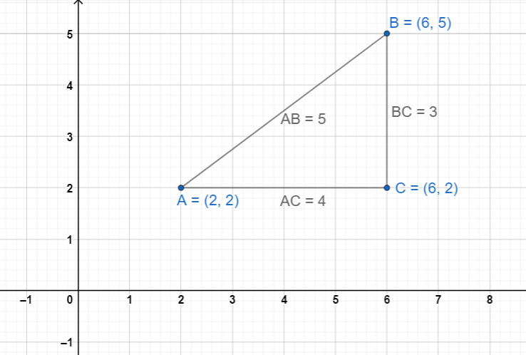
Distance Formula:
Example:
Example:
Collinearity of three points:
Three points P, Q and R are said to be collinear, if they lie in the same straight line.
i.e., PR = PQ + QR
i.e., PQ = PR + RQ
i.e., QR = QP + PR
If three points are not collinear, they always form a triangle.
Special Polygons:
(i) In Case of Triangle
(a) a right-angled triangle, if sum of squares of any two sides is equal to square of third side.
(b) an equilateral triangle, if all the three sides are equal.
(c) an isosceles triangle, if any two sides are equal.
(ii) In Case of Quadrilateral
(a) parallelogram, if opposite sides are equal and diagonals are not equal.
(b) rectangle, if opposite sides are equal and diagonals are equal.
(c) square, if all the four sides are equal and diagonals are equal.
(d) rhombus, if all the four sides are equal and diagonals are not equal.
Section Formula (Internal division only)
Midpoint Formula:
Point Dividing Two points in K : 1 Ratio:
Note:
If k is positive, the point divides the given points internally.
If k is Negative, the point divides the given points externally
Coordinates of the centroid of a triangle:
Points of Trisection:
If a line segment is divided into three equal parts by two points, the points are said to be the points of trisection.
In the given figure, the points R and S divide the line segment PQ into three equal parts i.e., PR=RS=SQ. The points R and S are said to be points of trisection.
Area of a Triangle:
The area of the triangle formed by the points
is calculated by the following expression.
Area of ∆PQR =
Area of Quadrilateral:
Area of a quadrilateral can be found by splitting up the quadrilateral into two triangles and sum up their areas.
Thus, area of quadrilateral PQRS = area of ∆PQR+ area of ∆PRS
Condition for collinearity of three points :
Three given points will be collinear, if the area of the triangle formed by these points is zero.
Rule to prove that three given points are collinear:
Step 1. Find the area of the triangle formed by the given points.
Step 2. Show that the area of the triangle formed by the given points is zero.
* The coordinates of the origin are O(0,0)
* The coordinates of any point on x-axis are (x, 0)
i.e., y=0 or ordinate is zero.
* The coordinates of any point on y – axis are (0, y) i.e., x=0 or abscissa is zero.
Mind Map Overal Idea Content Speed Notes Quick Coverage Data: A collection of numbers gathered to give someinformation. Recording Data:Data can becollected from different sources. Pictograph: The representation of data through pictures of objects. It helps answer the questions onthe data ata glance. (Scroll down till end of the page) Study Tools Audio, Visual &… readmore
Mind Map
Overal Idea
Content
Speed Notes
Quick Coverage
Data: A collection of numbers gathered to give someinformation. Recording Data:Data can becollected from different sources. Pictograph: The representation of data through pictures of objects. It helps answer the questions onthe data ata glance. (Scroll down till end of the page)
Study Tools
Audio, Visual & Digital Content
Bar Graph: Pictorial representation of numerical datain the formof bars (ractangles) of equal width and varying heights. We have seen that data is a collection of numbers gathered to give some information.
To get a particular information from the givendata quickly, thedata can be arranged ina tabular formusing tally marks. We learnt how a pictograph represents data in the formof pictures, objects or parts ofobjects.
We have also seen how to interpret a pictograph and answer the related questions.
We havedrawn pictographs using symbols to represent a certain number of items orthings.
We havediscussed how torepresent data byusing a bardiagram or abar graph.
Ina bar graph, bars of uniform width are drawn horizontally or vertically with equal spacing between them.
Thelength of eachbar gives therequired information.
To do this we also discussed the process of choosing a scale for the graph. For example, 1unit = 100students.
We havealso practised reading a given bargraph.
We have seen howinterpretations from thesame can bemade.
Mind Map Overal Idea Content Speed Notes Quick Coverage Content : (Scroll down till end of the page) Study Tools Audio, Visual & Digital Content Content … Key Terms Topic Terminology Term Important Tables Table: . Assessments Test Your Learning readmore
Mind Map Overal Idea Content Speed Notes Quick Coverage Content : (Scroll down till end of the page) Study Tools Audio, Visual & Digital Content Content … Key Terms Topic Terminology Term Important Tables Table: . Assessments Test Your Learning readmore