Your cart is currently empty!
Tag: Light – Reflection and Refraction
ATOMS AND MOLECULES | Study
STRUCTURE OF THE ATOM | Study
Light – Reflection and Refraction | Study

ATOMS AND MOLECULES | Study
Pre-Requisires
Test & Enrich
English Version Speed Notes
Notes For Quick Recap
- Atoms are the basic building blocks of matter.
- Different kinds of matter contain different kinds of atoms present in them.
- Protons were discovered by Ernest Rutherford, in his famous gold foil experiment.
- Electrons were discovered by J.J. Thomson, in his cathode ray tube experiment.
- Neutrons were discovered by James Chadwick. (Scroll down to continue …).
Study Tools
Audio, Visual & Digital Content
Laws of Chemical Combination: Antoine Laurent Lavoisier, is known as ‘Father of Modern Chemistry.
Lavoisier put forward the law of conservation of mass, which laid the foundation of chemical sciences.
Law of Conservation of Mass:Law of Conservation of Mass states that, “mass is neither created nor destroyed in a chemical reaction.
In other words, the mass of the reactants must be equal to the mass of products.
Law of Constant Proportions or Definite Composition: Law of Constant Proportions or Definite Composition states that, in a pure chemical substance, the elements are always present in definite proportions by mass.
Dalton’s Atomic Theory:
(i) Every element is composed of extremely small particles called atoms.
(ii) Atoms of a given element are identical, both in mass and properties.
(iiii) Different chemical elements have different kinds of atoms; in particular, their atoms have different masses.
(iv) The atoms neither be created nor be destroyed or transformed into atoms of other elements.
(v) Compounds are formed when atoms of different elements combine with each other in small whole number ratios.
(vi) The relative number and kinds of atoms in a given compound are constant.
Drawbacks of Dalton’s Atomic Theory:
(i) According to modern theory, an atom is not the ultimate indivisible particle of matter. Today, we know that atoms are divisible, they are themselves made-up of particles (protons, electrons, neutrons,etc.).
(i) In the case of isotopes of an element, the assumption that the atoms of the same element have the same mass does not hold good.
Atom: It is the smallest particle of an element that maintains its chemical identity throughout all chemical and physical changes.
The smallest unit of a substance which can exist independently is called a molecule.
Atomicity: It is defined as the number of atoms present in a molecule of an element or a compound.
Mono atomic: Molecule having only one atom is called mono atomic,
e.g., He, Ne, Ar.
Diatomic: Molecules made-up of two atoms are called diatomic, e.g., H₂, Cl₂, O₂, N2.
Triatomic: Molecules made-up of three atoms, called triatomic.
e.g., O3, H₂O, NO2.
Tetraatomic : Molecules made-up of four atoms, called tetra atomic.
e.g., P4, NH3, SO3
Polyatomic: Molecules made-up of five or more atoms, called polyatomic/
e.g., CH4.
Polyatomic: Any molecule which is made-up of more than four atoms is called polyatomic,
e.g., Sg.
Relative Atomic Mass: It is defined as the number of times one atom of an element is heavier than
(1/12)th of the mass of an atom of Carbon – 12.
Relative Atomic Mass (RAM) = Mass of an atom of an element/
¹/12 th mass of C-12
Molecular Mass: The molecular mass of a substance is the sum of the atomic masses of all atoms in a molecule of a substance,
e.g., molecular mass of water is 18 u.
The mole (or mol) is the SI unit of the amount of a substance. One mole is equal to the amount of substance that contains as many elementary units as there are atoms in 12 g of the carbon-12 isotope.
The elementary units may be atoms, molecules, ions, radicals, electrons, etc., and must be specified.
This number is called Avogadro’s number (No) or Avogadro’s constant
[NA = 6.0221367 x 10²³]. Generally,
Avogadro’s Number is rounded to 6.022 x 10²³.
For better understanding we can compare avogadro number with a dozen as:
One dozen oranges contain 12 oranges, similarly, 1 mole of hydrogen atoms contain 6.022 x 10²³ H atoms.
H₂O = 2 x H + 1 × O
= 2 x 1+1 x 16 = 2+16
= 18 amu or u.
By : 1 mole of a compound has a mass equal to its relative molecular mass expressed in grams.
1 mole = 6.022 × 10²³ number
= Relative mass in grams.
A molecule is the smallest particle of an element or a compound capable of independent existence under ordinary conditions. It shows all the properties of the substance.
A chemical formula of a compound shows its constituent elements and the number of atoms of each combining element.
Clusters of atoms that act as an ion are called polyatomic ions. They carry a fixed charge on them.
The chemical formula of a molecular compound is determined by the valency of each element.
In ionic compounds, the charge on each ion is used to determine the chemical formula of the compound.
Scientists use the relative atomic mass scale to compare the masses of different atoms of elements. Atoms of carbon-12 isotopes are assigned a relative atomic mass of 12 and the relative masses of all other atoms are obtained by comparison with the mass of a carbon-12 atom.
The Avogadro constant 6.022 × 10²³ is defined as the number of atoms in exactly 12 g of carbon-12.
The mole is the amount of substance that contains the same number of particles (atoms/ions/ molecules/formula units, etc.) as there are atoms in exactly 12g of carbon-12. Mass of 1 mole of a substance is called its molar mass.
The relative atomic mass of the atom of an element is the average mass of the atom as compared to 1/12th mass of one carbon-12 atom.
Hint: We know that chemical formulas can also be written using a criss-cross method. In the criss-cross method, the numerical value of the ion charge of the two atoms is crossed over, which becomes the subscript of the other ion. Using this technique, we will write the chemical formula of the given compounds.
Complete step by step answer:
Let’s us discuss about the given compound as,
A.Magnesium chloride
We have to remember that the atomic number of Magnesium is 12 and has a valency of 2.
It means it has two electrons in the outermost shell for bonding.
The atomic number of chlorine is 17 and has 7 electrons in the outermost shell.
It means it just needs one more atom for bonding.
Hence, we will use atoms of chlorine to bond with one atom of magnesium.
We can apply the criss-cross method for this compound as,

Therefore, the chemical formula of magnesium chloride is MgCl2
B.Calcium oxide
We have to know that the atomic number of calcium is 20 and has a valency of 2, it means it has 2 two atoms in the outermost shell for bonding.
The atomic number of Oxygen is 8
8 and has a valency of 2, it has 6 atoms in the outermost shell, it needs 2 more to complete the octet.
Hence, we need one calcium atom to bond with one oxygen atom.
We can apply the criss-cross method for this compound as,
Therefore, the chemical formula of magnesium chloride is CaO
C. Copper nitrate
We have to know that the atomic number of copper is 29 and has two atoms in the outermost shell for bonding. While a nitrate molecule has only one valence electron.
We need 2 nitrate molecules to satisfy the valency of 1 copper atom.
We can apply the criss-cross method for this compound as,
Therefore, the chemical formula of magnesium chloride is
Cu(NO3)2
D.Aluminium chloride
We have to know that the atomic number of aluminium is 13 and has a valency of 3 atoms and chlorine atom has a valency of 1. Since it has 7 electrons in the outermost shell.
Thus, we need 3 chlorine atoms to satisfy the valency of 1 aluminium atom.
We can apply the criss-cross method for this compound as,
Therefore, the chemical formula of magnesium chloride is AlCl3.
E.Potassium nitrate
We have to remember that the atomic number of potassium is 19 and has a valency of 1 and nitrate also has a valency of 1, since it needs one more atom to complete its octet. Hence, we need only one molecule of nitrate for one atom of potassium.
We can apply the criss-cross method for this compound as,
Therefore, the chemical formula of magnesium chloride is KNO3.
Note: As we know that the criss-cross method is the most efficient way to write the correct chemical formula of the molecule. It is generally used for finding out the formula of a bonding of a metal with a non-metal to form ionic bonds. Signs of the two ions are dropped, the ion value is crossed which becomes the subscript of the crossed atoms.
Hindi Version Dig Deep
Topic Level Resources
Sub – Topics
Select A Topic
Topic:
Chapters Index
Select Another Chapter
Assessments
Personalised Assessments
STRUCTURE OF THE ATOM | Study
Pre-Requisires
Test & Enrich
English Version Speed Notes
Notes For Quick Recap
- Atoms are the basic building blocks of matter.
- Different kinds of matter contain different kinds of atoms present in them.
- Protons were discovered by Ernest Rutherford, in his famous gold foil experiment.
- Electrons were discovered by J.J. Thomson, in his cathode ray tube experiment.
- Neutrons were discovered by James Chadwick. (Scroll down to continue …)
Study Tools
Audio, Visual & Digital Content
Charged Particles in Matter
- Whenever we rub two objects together, they become electrically charged.
- This is because atoms contain charged particles in them.
- Therefore, atoms can be divided further into particles i.e proton, electron and neutron.
Atoms consist of an equal number of protons and electrons.
Protons exist in the interiors of the atom and electrons exist in the exteriors of the atom. Therefore, electrons can be removed from an atom.
Since electrons exist in the exteriors of the atom they can be removed from an atom.
Dalton’s Atomic Theory
The postulates of the atomic theory by John Dalton
- The matter is made up of tiny particles called Atoms that cannot be divided.
- Atoms are never formed or destroyed during a chemical reaction.
- Atoms of an element exhibit the same nature.
- Atoms of the same element have equal size, mass and they exhibit similar chemical properties.
- Atoms of different elements exhibit variant chemical properties.
- Atoms form compounds by combining in a ratio of whole numbers.
- A compound contains molecules in which a constant number and types of atoms are present.
Failure of Dalton’s Atomic Theory
Dalton suggested that atoms can neither be created nor destroyed and are indivisible.
But the discovery of electrons and protons in atoms disproved this aspect of Dalton’s theory.
Thomson’s Model of an Atom
According to J.J. Thomson, the structure of an atom can be compared to Christmas pudding.
According to this model the electrons are present inside a positive sphere.

An atom is composed of a positively charged sphere in which electrons are embedded.
Atoms are neutral as the positive and negative charges are equal in number.
Rutherford’s Model of an Atom

Rutherford’s Experiment
Rutherford experimented by passing alpha rays through a thin gold foil.
He expected that the gold atoms would deflect the Alpha particles.
Observations Inferences Alpha particles which had high speed moved straight through the gold foil Atom contains a lot of empty space Some particles got diverted a by small angles Positive charges in the atom are not occupying much of its space Only one out of 12000 particles bounced back The positive charges are concentrated over a particular area of the atom. Based on his experiment Rutherford gave the nuclear model of an atom as the following.
Rutherford’s Atomic Model
Rutherford’s Atomic Model is known as Planetary Atomic Model and Nuclear Atomic Model.
According to Rutherford’s Atomic Model:
- Atoms contain a lot of unoccupied space
- The center of the atom is highly positive , Rutherford named it as nucleus
- The atom contains an equal amount of positive and negative charges.
Nucleus of Atom

The nucleus is located at the center of the atom.
All the mass of the atom is because of the nucleus.
The electrons revolve around the nucleus in circular parts which called Orbits
The size of an atomic nucleus is much smaller than its atom.
Drawbacks of the Nuclear Atomic Model
The Rutherford’s Atomic Model failed to explain how an atom remains stable despite having positive and negative charges present in it.
Maxwell’s theory of radiation if any charged particle moves in a circular motion it radiates energy.
So, if electrons move in a circular motion around the nucleus they should radiate some energy as a result this decreases at the speed of the electrons. As a result, they would fall into the nucleus and the nucleus should collapse because of its high positive charge.
But it is not happening because the matter is not collapsing.
Nucleons: The subatomic particles present in the nucleus are collectively called Nucleons. Protons and Neutrons are nucleons.
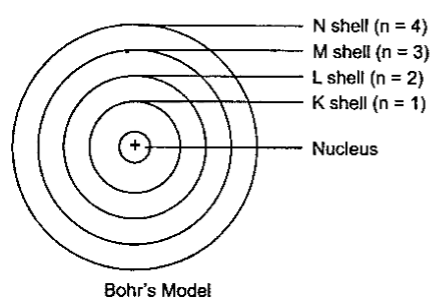
Bohr’s Model of an Atom
Bohr Atomic Model states as the following:

- Electrons revolve around the nucleus in particular circular paths, called orbits.
- The electrons do not emit any energy while moving in their orbits.
- The orbits are also called Energy Levels.
- Energy Levels or Orbits are represented by using letters or numbers as shown in the figure.
Neutron:
J. Chadwick discovered Neutron, a subatomic particle of an atom.
Neutron carries no charge.
Subatomic Particles of Atom
Electrons Electron carry a negative charge Protons Protons carry a positive charge Neutrons Neutrons are neutral Electronic Configuration: The distribution of electrons in different shells or orbits is called Electronic Configuration.
- If Orbit number = n
- Then number of electrons present in an Orbit = 2n2
- So, for n =1
- Maximum electrons present in shell – K = 2 * (1)2 = 2
- The outermost shell can contain at most 8 electrons.
- The shells in an atom are filled in sequence.
- Thus, until the inner shells of an atom are filled completely the outer shells cannot contain any electrons.
Valency
- Valence Electrons – Electrons existing in the outermost orbit of an atom are called Valence Electrons.
- The atoms which have completely filled the outermost shell are not very active chemically.
- The valency of an atom or the combining capacity of an atom is given by the number of elements present in the outermost shell.
- For Example, Helium contains two electrons in its outermost shell which means its valency is two. In other words, it can share two electrons to form a chemical bond with another element.
- What happens when the outermost shell contains a number of electrons that are close to its maximum capacity?
Valency in such cases is generated by subtracting the number of electrons present in the outermost orbit from octet (8). For example, oxygen contains 6 electrons in its outermost shell. Its valency is calculated as: 8 – 6 = 2. This means oxygen needs two electrons to form a bond with another element.
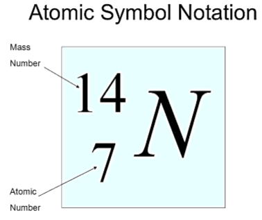
Representation Element:

Atomic Number of an Element
Atomic Number (Z) = Number of protons in an atom
Mass Number of an Element
Mass Number = Number of protons + Number of neutrons
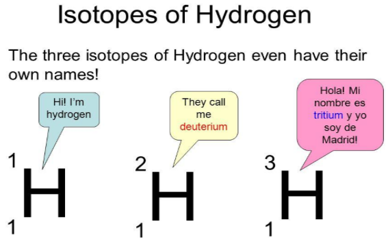
Isotopes

- The atoms of an element can exist in several forms having similar atomic numbers but varying mass numbers.
- Isotopes are pure substances.
- Isotopes have a similar chemical nature.
- Isotopes have distinct physical characteristics.
Use of Isotopes:
1. The fuel of Nuclear Reactor – Isotope of Uranium
2. Treatment of Cancer – Isotope of Cobalt
3. Treatment of Goiter – Isotope of Iodine
Example: Consider two atomic species namely U and V. Are they isotopes?
U V Protons 5 5 Neutrons 5 6 Mass Number 5 + 5 = 10 5 + 6 = 11 Atomic Number 5 5 From the above example, we can infer that U and V are isotopes because their atomic number is the same.
Isobars
The atoms of several elements can have a similar mass number but distinct atomic masses. Such elements are called Isobars.

Hindi Version Dig Deep
Topic Level Resources
Sub – Topics
Select A Topic
Topic:
Chapters Index
Select Another Chapter
Assessments
Personalised Assessments
Light – Reflection and Refraction | Study
Pre-Requisires
Test & Enrich
English Version Speed Notes
Notes For Quick Recap
Study Tools
Audio, Visual & Digital Content
Full Notes
_____________________________________________
Introduction To Reflection and Refraction of Light
Light travels in a straight path in a uniform medium.
The light that bounces back when it strikes a smooth or rough Opaque surface is called reflection of light.
Light bends when it travels from one transparent medium to the other transparent medium at the surface that separates the two transparent media. Such a phenomenon is called Refraction of light.
Reflection of light
Reflection of light is of two types they are:
(i) Specular or Regular
(ii) Diffused or Irregular Reflection.
(i) Regular reflection
Definition: Regular reflection, also known as specular reflection, occurs when light rays strike a smooth surface and reflect at a consistent angle.
Key Characteristics:
Surface Type: Smooth surfaces, such as mirrors or calm water.
Angle of Incidence = Angle of Reflection: The angle at which the incoming light strikes the surface (angle of incidence) is equal to the angle at which it reflects off the surface (angle of reflection).
Image Formation: Produces clear and defined images, as the light rays remain organized.
Applications: Used in mirrors, optical instruments, and various imaging technologies.(ii) Diffused or Irregular reflection
Irregular reflection, or diffuse reflection, occurs when light rays strike a rough or uneven surface, scattering the light in multiple directions.
Key Characteristics:
Surface Type: Rough surfaces, such as paper, walls, or unpolished wood.
Scattering of Light: Light rays reflect at various angles, leading to a diffuse spread of light.
No Clear Image: Does not produce a clear image; instead, it illuminates the surface uniformly.
Applications: Used in everyday scenarios for visibility, such as in rooms and outdoor environments, where light needs to be diffused for better illumination.Laws of Reflection

In the case of reflection, The light obeys two laws of reflection as follows.
(i) angle of incidence, i is equal to the angle of reflection, r. Mathematically, it is represented as: ∠i = ∠r
(ii) The incident ray, The normal ray and reflected ray lie in the same plane.
The image formed by a mirror, such as a plane mirror and a spherical mirror are due to regular reflection of light.
Based on the nature of images formed by the mirrors, the images are of two types they are:
- Real images
- Virtual Images
Real images are the images which can be captured onto a screen.The real images are formed when the light rays really meet at a point.
Example, Slide projector in a cinema hall forms an image on the screen.
Virtual images are the images which cannot be caught on a screen.
The virtual images are formed when the light ranys really do not meet at a point.
But they appear to be images formed by the meeting of light rays.
Note:
- The virtual images can be viewed with our naked eyes.
For example, the images formed due to reflection of light by a plane mirror of a dressing table and parking (convex) mirror.
Types of Mirrors
Generally the mirrors are classified into the following two types as:
- Plane mirrors
- Curved mirrors.
Generally mirrors refer to plane mirrors. But if the surface of a mirror is curved it is said to be a curved mirror.
Examples:
Concave mirror, convex mirror and Elliptical mirror etc.,
If the curvature of a mirror is a huge sphere, the mirror is said to be a spherical mirror.
Examples:
Concave mirror, convex mirror
Spherical mirrors are a special type of curved mirror.
Characteristics of Image Formed By A Plane Mirror
*The image formed by a plane mirror is unmagnified, virtual and erect.
*The image formed by a plane mirror has right-left reversal known as lateral Inversion.
*Focal length of a plane mirror is infinite.
*Power of a plane mirror is zero.
*If a plane mirror is turned by an angle, θ , the reflected ray turns by 2θ .
*The least size of a plane mirror to view an object is equal to half the size of the object.
Curved – Mirrors
A mirror that has a curved reflecting surface is said to be a curved mirror.
Spherical Mirrors

*Pole – The geometric centre of the reflecting surface of a spherical mirror is its pole. It is represented by P.
*Centre of curvature – The centre of the curvature of the reflecting surface of a spherical mirror is known as centre of curvature. It is represented by C.
*Centre of curvature in a convex mirror lies behind the mirror.
*But it lies in front of the mirror in a concave mirror.
*Radius of curvature – The radius of the reflecting surface of the spherical mirror is known as radius of curvature. It is represented by R.

*Principal axis – Straight line passing through the pole and centre of curvature in a spherical mirror is known as principal axis.
*Principal focus – The reflected rays appear to come from a point on the principal axis, known as principal focus. Principal focus (F) is the point on the principal axis, where a parallel beam of light, parallel to the principal axis after reflection converges in the case of a concave mirror and appears to diverge from in the case of a convex mirror.
*Focal length – The distance between the pole and the principal focus in a spherical mirror, known as focal length and it is represented by f.
*Note: Radius of curvature is twice the focal length (R=2f). In other words, The focal length is half the radius of curvature.
*Focal plane: A plane, drawn perpendicular to the principal axis such as it passes through the principal focus is called the focal plane.
*Aperture – The diameter of the reflecting surface is known as its aperture. The size of the mirror is called its aperture. In other words It is also defined as the effective diameter of the light reflecting area of the mirror.
If the curvature of a mirror is a huge sphere, the curved mirror is said to be a spherical mirror.
The reflecting surface of a mirror can be curved inwards or curved outwards.
Curved mirrors and Spherical mirrors are classified into the following two types:
- Concave mirrors
- Convex mirrors.
A curved mirror or a spherical mirror whose reflecting surface is curved inward is known as a concave mirror.
Conversely, A curved mirror or a spherical mirror whose reflecting surface is outward curved is known as a convex mirror.
Terms Associated with Spherical Mirrors
*Pole – The geometric centre of the reflecting surface of a spherical mirror is its pole. It is represented by P.
*Centre of curvature – The centre of the curvature of the reflecting surface of a spherical mirror is known as centre of curvature. It is represented by C.
*Centre of curvature in a convex mirror lies behind the mirror.
*But it lies in front of the mirror in a concave mirror.
*Radius of curvature – The radius of the reflecting surface of the spherical mirror is known as radius of curvature. It is represented by R.
*Principal axis – Straight line passing through the pole and centre of curvature in a spherical mirror is known as principal axis.
*Principal focus – The reflected rays appear to come from a point on the principal axis, known as principal focus. Principal focus (F) is the point on the principal axis, where a parallel beam of light, parallel to the principal axis after reflection converges in the case of a concave mirror and appears to diverge from in the case of a convex mirror.
*Focal length – The distance between the pole and the principal focus in a spherical mirror, known as focal length and it is represented by f.
*Note: Radius of curvature is twice the focal length (R=2f). In other words, The focal length is half the radius of curvature.
*Focal plane: A plane, drawn perpendicular to the principal axis such as it passes through the principal focus is called the focal plane.
*Aperture – The diameter of the reflecting surface is known as its aperture. The size of the mirror is called its aperture. In other words It is also defined as the effective diameter of the light reflecting area of the mirror.
Image Formation by Spherical Mirrors
Rules for Construction of Ray Diagrams for Spherical Mirrors
Rule 1: An incident light ray parallel to the principal axis, passes through the principal focus or appears to pass through the principal focus after reflection.
Rule 2: An incident light ray that passes through the principal focus or appears to pass through the principal focus, travel parallel to the principal axis after reflection.
Rule 3: An incident light ray that passes through the center of curvature or appears to pass through the center of curvature, after reflection and retraces its initial path.
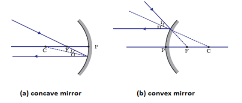
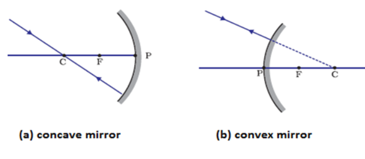
Rule 4: A ray incident obliquely to the principal axis towards the pole, P of the curved mirror (concave mirror and convex mirror) is reflected obliquely.
Note:
The incident and reflected rays always follow the laws of reflection at the point of incidence (P) making equal angles with the principal axis.
that passes through the center of curvature or appears to pass through the center of curvature, after reflection and retraces its initial path.
Reflection By Concave Mirrors
Incident Ray Reflected Ray Parallel to principal axis Passes through focus Passes through C Retraces its path Passes through focus parallel to principal axis Strikes the pole at an angle with principal axis Makes the same angle with the principal axis. Reflection by Convex Mirror
Incident Ray Reflected Ray Parallel to principal axis Appears to pass through focus Directed towards the focus Appears to pass parallel to principal axis Strikes the pole at an angle with principal axis Makes the same angle with principal axis Concave Mirror

Terms Associated With Concave Mirror
The geometric centre of a concave mirror is called its pole.
The centre of the sphere from which the concave mirror was cut is called the centre of curvature of the concave mirror.
The centre of curvature of the reflecting surface of a concave mirror is called the centre of curvature of the concave mirror.
The distance from any point on the concave mirror to its center of curvature is called the radius of curvature of the concave mirror.
An imaginary line passing through the center of curvature and the pole of the concave mirror is called the principal axis of the concave mirror.
The area of a concave mirror that is exposed to incident light is called the aperture of the concave mirror.
The length along the principal axis from the pole to the principal focus is called the focal length of the concave mirror.
If an object is placed close to a concave mirror such that the distance between the mirror and the object is less than its focal length, then a magnified and virtual image is formed.
This property of the concave mirror is used in many applications such as a dentist mirror to view the inner parts of the mouth clearly and a shaving mirror.
Concave mirrors converge the light incident on them and hence are called converging mirrors.
Image Formation by Concave Mirror
Location of an image of an object formed by a concave mirror by drawing the ray diagrams.
*We can locate the image of an object formed by a concave mirror by drawing the ray diagrams.
*The intersecting point of at least two reflections will give the position of image of the point object.
*The following rays can be used to draw the ray diagrams.
*A ray parallel to the principal axis of a concave mirror.
*A ray passing through the focus of the concave mirror
*A ray which is passing through the centre of curvature of a concave mirror
*A ray incident obliquely to the principal axis on a concave mirror.
Rules for Drawing Ray Diagrams in Spherical Concave Mirrors
A ray parallel to the principal axis of a concave mirror.

*A ray parallel to the principal axis of the concave mirror reflects through its focus.
A ray passing through the focus of the concave mirror.

*A ray passing through the focus of the concave mirror reflects parallel to the principal axis.
A ray which is passing through the centre of curvature of a concave mirror

*A ray which is passing through the centre of curvature of a concave mirror reflects back on the same path.
*A ray incident obliquely to the principal axis on a concave mirror.

A ray when incident obliquely to the principal axis on a concave mirror also reflects obliquely.
Concave Mirrors – Ray Diagrams
Depending on the position of the object in front of the concave mirror, the position, size and the nature of the image varies.
We can represent the images formed by a Concave Mirror using Ray Diagrams.
Object at infinity

A real, inverted, highly diminished image is formed at the focus, F, in front of the concave mirror.
Object beyond C

A real, inverted, diminished image is formed between C and F, in front of the concave mirror.
Object at C
A real, inverted, same sized image is formed at C, in front of the concave mirror.
Object between C and F
A real, inverted, enlarged image is formed beyond C, in front of the concave mirror.
Object at F
A real, inverted, highly enlarged image is formed at infinity, in front of the concave mirror.
Object between F and P
A virtual, erect and enlarged image is formed behind the concave mirror.
Image Formation by a Concave Mirror
Object Location Image Location Nature of Image Infinity At F Real, InvertedHighly DiminishedMagnification<<1 
Beyond C Beyond F and C Real, Inverted, Diminished
Magnification<1
At C At C Real, Inverted, Equal to size of object
Magnification=1
Between C and F Beyond C Real, Inverted, Magnified
Magnification>1
At F Infinity Real, Inverted, Highly Magnified
Magnification>>1
Between F and P Behind the mirror Virtual, Erect, Magnified,
Magnification>1
Uses of Concave Mirrors
- Concave mirrors are used as shaving mirrors to see a larger image of the face.
- Dentists use concave mirrors to view a magnified view of the interior parts of the mouth.
- ENT doctors use them for examining the internal parts of the ear, nose and throat.
- They are used as reflectors in the headlights of vehicles, searchlights and in torch lights to produce a strong parallel beam of light.
- Huge concave mirrors are used to focus sunlight to produce heat in solar furnaces.
Convex Mirror
A spherical mirror whose reflecting surface is curved outward is known as a convex mirror.

Terms Associated With Convex Mirror
The geometric centre of the curvature of the convex mirror is called its pole.
The centre of curvature of the reflecting surface of a convex mirror is called the centre of curvature of the convex mirror.
The distance from any point on the reflecting surface of a convex mirror to its centre of curvature is called radius of curvature of the convex mirror.
An imaginary line passing through the centre of curvature and the pole of the convex mirror is called the principal axis of the convex mirror.
The reflected rays, when projected backwards, appear to meet at a point on the principal axis. This point is called the principal focus. The length along the principal axis from the pole to the principal focus is called the focal length of the concave mirror.
The area of a convex mirror that is exposed to incident light is called the aperture of the convex mirror.
If the aperture of a convex mirror is small, then Convex mirrors, such as the rear view mirrors of cars and bikes, always form erect, virtual, and diminished images.
The location of the object does not affect the characteristics of the image formed by a convex mirror.
When an object approaches a convex mirror, the image formed by the mirror also approaches the mirror, but not proportionately. Because of this it is mentioned as “Objects seen in the mirror are closer than they appear” on the outside rear view mirrors of vehicles.
Image Formation by Concave Mirror
ray diagrams –
- We can locate the image of an object formed by drawing a ray diagram.
- The intersecting point of at least two reflections will give the position of image of the point object.
The two rays that can be used to draw the ray diagram are:
- A ray parallel to the principal axis.

- A ray parallel to the principal axis reflects
- It passes through the focus in case of a concave mirror.
- A ray parallel to the principal axis. On reflection it appears to diverge from principal focus after reflection in case of a convex mirror.
- A ray passing through the focus of the concave mirror. On reflection it becomes parallel to the principal axis due to reflection.

- A ray directed towards the focus of convex mirrors. On reflection it becomes parallel to the principal axis due to reflection.
- A ray which is passing through the centre of curvature of a concave mirror. It reflects back on the same path.

- A ray which is directed towards the centre of curvature of a convex mirror. It reflects back on the same path.
- A ray when incident obliquely to the principal axis on a concave x mirror is also reflected obliquely.

- A ray when incident obliquely to the principal axis on a convex mirror is also reflected obliquely.
Reflection by Convex Mirror
Incident Ray Reflected Ray Parallel to principal axis Appears to pass through focus Directed towards the focus Appears to pass parallel to principal axis Strikes the pole at an angle with principal axis Makes the same angle with principal axis Image Formed By A Convex Mirror
Irrespective of the position of the object, a virtual, erect and diminished image is formed between F and P, behind the convex mirror.

Uses of Convex Mirrors
Convex mirrors are used as:
- rear view mirrors in automobiles and in ATM centres as it covers a wide area behind the driver.
- reflectors in street light bulbs as it diverges light rays over a wide area.
- Rear view mirrors of vehicles and the ones used.
Sign Convention for Spherical Mirrors
- Object is always considered at the left side of the mirror
- Distances measured in the direction of the incident ray are taken as positive.
- Distances measured in the direction opposite to that of the incident rays are taken as negative.
- All distances are measured from the pole of the mirror.
- Distances measured along the y-axis above the principal axis are taken as positive.
- Distances measured along the y-axis below the principal axis are taken as negative.
Table Showing Sign Convention
Type of Mirror Object Distance, u Image Distance, v Focal length, f Radius of Curvature, R Height of the Object, hO Height of the Image, hi Real Virtual Real Virtual Concave mirror –Ve –Ve +Ve –Ve –Ve +Ve –Ve +Ve Convex mirror –Ve Virtual image +Ve +Ve +Ve +Ve Virtual image +Ve 
Mirror Formula
The relation between the focal length (f), object distance (u) and the image distance (v) is given by:

Magnification
The ratio of the height of the image in a spherical mirror, to the height of the object is called magnification (m)
Magnification,m = Height of Image, HHeight of Object, i= Image Distance, HObject Distance, i
The distance from the principal focus to the pole of the mirror is the focal length of the mirror and is equal to half the radius of curvature, which is the distance between the centre of curvature and the pole.
For a real image object distance (u) and the image distance (v) are negative and the magnification is negative.
If the magnification of an image is negative it does mean that the image is real and inverted.
On the other hand for a virtual image object distance (u) is negative and image distance (v) is positive and hence the magnification is positive, i.e., the image is erect.
If the magnification of an image is positive it does mean that the image is virtual and erect.
- If the magnification is less than 1 The image formed is diminished in size.
- If the magnification is more than 1 The image formed is magnified in size.
- If the magnification is equal to 1 The image formed is equal to the object in size.
Convex mirrors diverge the light incident on them and hence they are called the diverging mirrors.
Due to this they always form diminished, virtual and erect images irrespective of the position of the object in front of them.
Thus, the magnification caused by these mirrors is always less than one.
The field of view for a convex mirror is greater than that for a plane mirror, the aperture being the same.
Hence, convex mirrors are used as rear-view mirrors in vehicles.
It is also installed behind automated teller machines as a security measure.
The field of view for a convex mirror is greater than that for a plane mirror, the aperture being the same.
Hence, convex mirrors are used as rear-view mirrors in vehicles. It is also installed behind automated teller machines as a security measure.
The images formed by convex mirrors are always diminished, virtual and erect, irrespective of the position of the object.
Differences Between Convex Mirror and Concave Mirror
Convex Mirror Concave Mirror Convex mirror is curved outwards. 1. Concave mirror is curved inwards. The focal point of the convex mirror is behind the mirror. 2. The focal point of the concave mirror is in front of the mirror. In convex mirrors the image is always virtual, upright and smaller than the object. 3. In the case of concave mirrors different types of images are formed on different locations of the object. The image is upside down (inverted) and far away but if we bring the object close to the mirror then the image will be larger and upright. Convex mirrors are used in cars (as passenger-side mirrors since they provide upright and wide view), they are also used in camera phones, for safety measures there are also used in roads and driveways.Besides these convex mirrors are found in many hospitals, schools etc. as hallway safety mirrors. 4. Concave mirrors are used in telescopes. These are also used as make up and shaving mirrors since these provide larger images.
Besides these concave mirrors are used by dentists and also used in headlights of cars, solar devices, satellite dishes etc.Refraction Of Light At Plane Surfaces
Introduction
Light bends while traveling from one medium to another. Since the refraction of light occurs at the surface joining two media, the refraction is a surface phenomenon.
The bending of light when it travels from one medium into another is called refraction of light.
The reason for refraction of light is the change in speed of light.
The speed of light in an optically rarer medium is more than that in an optically denser medium.
- Light rays passing from rarer to denser medium bends towards the normal. This makes the angle of incidence (angle between the incident ray and the normal at the point of incidence) more than that of the angle of refraction (angle between the normal and the refracted ray).
- Light rays passing from denser to rarer medium bends away from the normal. This makes the angle of incidence (angle between the incident ray and the normal at the point of incidence) less than that of the angle of refraction (angle between the normal and the refracted ray).
- The extent to which a light ray bends depends on the refrangibility of the ray with respect to the medium.
- In other words, the extent to which a light ray bends depends on the refractive index of the respective medium.
- The ratio of velocity of light in vacuum to that in a medium is termed as the absolute refractive index (m) of the medium or simply termed as the refractive index of the medium.
- Refractive index (m) of the medium is the measure of the ability of light to get bent in the given medium.
- Measuring the speed of light is difficult.
- We can determine the refractive index using Snell’s law
- According to Snell’s law,
- The refraction of light obeys the following two laws:
- The incident ray, the refracted ray and the normal at the point of incidence all lie in the same plane.
- The ratio of the sine of the angle of incidence to the sine of the angle of refraction is a constant. This constant is called the index of refraction or refractive index.
Mathematically, (sin i)/(sin r)= (n2/n1) (Or)
(sin i)/(sin r)= (1n2), where (1n2), is the refractive index of the medium 2, in which the refracted ray travels, with respect to medium 1, in which the incident ray travels.
This law is credited to Willebrord Snell and is, therefore, called Snell’s law.
If wng is the refractive index of glass w.r.t. water, ang be the refractive index of glass w.r.t. air and anw be the refractive index of water w.r.t. air ,then
wng= ang/anw
- If the light ray retraces its path while traveling from denser to rarer, the angle of incidence is lesser than that of the refraction. This is the principle of reversibility.
The extent to which a light ray bends depends on the refrangibility of the ray with respect to the medium.
The ratio of velocity of light in vacuum to that in a medium is termed as the absolute refractive index (m) of the medium. Absolute refractive index (m) of the medium is the measure of the ability of light to get bent in the given medium.
Measuring the speed of light is difficult.
We can determine the refractive index using Snell’s law
According to Snell’s law,

Refraction of Light At A plane Surface
The bottom of a water glass appears to rise upwards when viewed normally. This is due to the vertical shift of the bottom of the glass, which takes place because of refraction.
Refraction of Light At Glass Slab
When a light ray, incident at an angle, passes through a glass slab, the emergent ray shifts laterally, known as lateral shift.
The lateral shift depends on the thickness and refractive index of the glass slab.
If the angle of incidence increases gradually, the angle of refraction also increases.
But, at a particular angle of incidence in the denser medium, the refracted ray emerges along the surface. That particular angle is known as the critical angle.
If the angle of incidence is greater than the critical angle, the ray undergoes Total Internal Reflection.
The formation of Mirages in deserts is due to total internal reflection of light.
n=cv
n=(Speed of light in vacuum)/( speed of light in the medium)
As light travels from one medium to another, the frequency of light does not change.
Lenses
A lens is a piece of transparent optical material with one or two curved surfaces to refract light rays.
The simplest lens has two spherical surfaces close enough together that we can neglect the distance between them. Such a lens is called a thin lens.
The two common types of lenses are Converging lens or Convex lens.
It should be noted that, if the above lenses are surrounded by a material with a refractive index greater than that of the lens, the convex lens gets converted into a concave lens and vice versa.
A lens may converge or diverge light rays to form an image.
Types of Lenses
A bi-convex lens is one with a surface that is bulged outwards on both the sides. It is generally referred to as a convex lens.
Another type of lens is a bi-concave lens that has two inward bent surfaces. It is generally referred to as a concave lens.
A Plano-convex lens has a convex surface on one side and a plane surface on the other.
A Plano-concave lens is the one that has a concave surface on one side and a plane surface on the other.
A concavo-convex lens has a concave surface on one side and a convex surface on the other.
Convex and concave lenses are important as they are more commonly used than the other types of lenses.
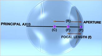
Terms Used for Lens
Center of Curvature: The center of the imaginary glass sphere of which the lens is a part, is called center of curvature.
Principal Axis: An imaginary line joining the centers of curvature of the two spheres, of which lens is a part, is called Principal Axis.
Optic Center: A point within the lens, where a line drawn through the diameter of lens meets the principal axis, is called the optic center.
Principal Focus for Convex Lens: It is a point on the principal axis of a convex lens, where parallel beams of light rays, traveling parallel to the principal axis, after passing through the lens actually meet.
Principal Focus for Concave Lens: It is a point on the principal axis of a concave lens, from where a parallel beam of light rays, traveling parallel to the principal axis, after passing through the lens, appears to come.
Focal Length: The distance between principal focus and optical centre is called focal length.
Aperture: The effective diameter of the lens through which refraction takes place is called aperture of lens.
Optic centre is a point on the axis of a lens such that any light ray passing through this point emerges without refraction.
• Principal focus is a point on the axis of a lens.
• Principal focus is also known as the focal point.
Spherical Lenses
Convex Lense
A lens in which both the surfaces are convex, is known as convex lens.
Since the convex lens converges the light incident on it. It is called the converging lens.
The convex lenses form different types of images depending on its relative position with respect to the position of the object in front of them.
Thus, the magnification produced by these lenses varies.
Concave Lense
A lens in which both the surfaces are concave, is known as a concave lens.
Since the concave lens diverges the light incident on it. It is called the diverging lens.
Due to this the concave lenses always form diminished, virtual and erect images irrespective of the position of the object in front of them.
Thus, the magnification produced by these lenses is always less than one.
Image Formation by Refraction Of Light Through Spherical Lenses
Behaviour of Light Rays Propagating Through a Convex Lens
Rules for Construction of Ray Diagrams for Convex Lens

Rule 1: All rays parallel to the
principal axis of a convex lens passes through the principal focus after refraction.
Rule 2: A ray of light passing through the focus of a convex lens becomes parallel to the principal axis after refraction.
Rule 3: A ray of light passing through the optical center of a convex lens passes un deviated after refraction.

Rule 4:
Note: A convex and a concave lens can be supposed to be made-up of prisms.
Image Formation by a Convex Lens
Object Location Image Location Nature of Image Uses Infinity At F2 • Real• Inverted• Highly Diminished Telescopes Beyond 2F1 Between F2 and 2F2 • Real• Inverted• Diminished In a camera, In eye while reading At 2F1 At 2F2 • Real• Inverted• Equal to size of object Photocopier Between 2F1 and F1 Beyond 2F2 • Real• Inverted• Magnified Projector, Microscope objective At F1 Infinity • Real• Inverted• Highly Magnified Spotlights Between F and O On the same side of lens as the object • Virtual• Erect• Magnified Magnifying glass, eye lenses spectacles for short distances. Concave Lens:
A lens, in which both the surfaces are concave, is known as a concave lens.
An image formed by a concave lens is always diminished due to the divergence of rays. This is why concave lenses are widely used to correct eye defects such as myopia.
A concave lens is also known as a diverging, reducing, negative and myopic or minus lens.
Behaviour of Light Rays Propagating Through a Concave Lens.
Behaviour of Light Rays Propagating Through a Concave Lens
Rules for Construction of Ray Diagrams for Concave Lens
Rule 1: All rays parallel to the principal axis of a concave lens diverge such that they are coming from the principal focus after refraction.
Rule 2: A ray of light directed towards the focus of a concave lens becomes parallel to the principal axis after refraction.
Rule 3: A ray of light passing through the optical center of a concave lens passes un deviated.

Note: A convex and a concave lens can be supposed to be made-up of prisms.
The lens formula defines the relationship between the focal length of the lens (f), the distance of the object from the optic center (u) and the distance of the image from the optic center (v):
Location and Characteristic of the Images Formed by a Concave Lens
Sign convention for spherical lenses:
- All distances on the principal axis are measured from the optic center of the lens.
- All distances measured above the principal axis are taken as positive. Thus, height of an object and that of an erect image are positive and all distances measured below the principal axis are taken as negative.
- The distances measured in the direction of the incident light are taken as positive (+)
- The distances measured in the direction opposite to that of the incident light are taken as negative (-).
Table Showing Sign Convention In Concave & Convex Mirrors & Lenses
Type of Mirror Object Distance, u Image Distance, v Focal length, f Radius of Curvature, R = f/2Power = 1/P Height of the Object Height of the Image Real Virtual Real, Inverted Virtual, Erect Concave Mirror -Ve +Ve -Ve -Ve +Ve -Ve +Ve Convex Mirror -Ve +Ve -Ve +Ve +Ve -Ve +Ve Convex Lens -Ve +Ve -Ve +Ve +Ve -Ve +Ve Concave Lens -Ve +Ve -Ve -Ve +Ve -Ve +Ve Lens Formula and Sign Conventions
Magnification of lens (m)
Magnification is the ratio of the image size to the object size. It is also measured as the ratio of image distance to object distance.
m = Size of the image / Size of Object
Or
m = Image distance / Object distance
If m = 1; image size = object size
If m > 1: image size > object size
If m < 1: image size < object size
Power of Lens (P)
• The converging or diverging capacity of a lens is ascertained by its power
• Power of a lens is the reciprocal of its focal length expressed in meter.
P=1f
( measured in meters).
• SI Unit of power of a lens is dioptre (D).
• Power of a convex lens is positive and that of a concave lens is negative.
Differences Between Convex Lens and Concave Lens:
Formulae:
- Magnification = Image distance / Object distance
m=vu
- Magnification = Image Height / Object Height
- Image distance / Object distance = Image Height / Object Height
- If magnification is <1, the image is Diminished or minimised or shrunk.
- If magnification= 1, the size of the image is equal to the size of the object.
- If magnification is >1, the image is Magnified or enlarged or bigger.
- If magnification is <1, the image is Diminished or Shrunk or Smsller.

- ⇒ m=vu ⇒ u=vm
- ⇒ m=vu ⇒ v=mu
- ⇒ 1f=1v1(vm) ⇒ 1f=1v-mv ⇒ 1f=1-mv
- ⇒ f=v1-m
- ⇒ f=mu1-m
- ⇒ Power of lens=1Focal Length
- ⇒ Power of lens x Focal Length =1
- ⇒ P=1f
For Spherical Mirrors :
P= 2R=1f=1v+ 1u=1-mv =(m-1)mu-(m-1)-mu
For Spherical Lenses :
P= 2R=1f= 1v-1u=1-mv = 1-mmu
- For Spherical Mirrors :
- R2=f= uvu+v
- 2R=1f= 1v + 1u
- m=-vu
- If m > 1, Image is magnified
- If m < 1, Image is diminished
- If m = 1, Image is Equal to size of object
- Sign of magnification, m is negative for real image.
- Sign of magnification, m is positive for virtual images.
- The number indicates how many times magnification.
- Where the sign indicates whether the image is virtual erect or real inverted.
- v=-mu
- m=hih0
- For Spherical Lenses :
- R2=f= uvu-v
- 2R=1f= 1v – 1u
- m=vu
- m=hih0
- If m > 1, Image is magnified
- If m < 1, Image is diminished
- If m = 1, Image is Equal to size of object
- Sign of magnification, m is negative for a real, Inverted image.
- Sign of magnification, m is positive for virtual, Erect image.
- The number indicates how many times magnification.
- Where the sign indicates whether the image is virtual erect or real inverted.
- P= 2R=1-mv = 1-mmu
- 1f= 1v+1u
- If m is Negative image is real
- If m is Positive image is Virtual
- If height of the image is equal to height of the object m = 1, that is image height is equal to the object height
- If height of the image is greater than height of the object, then m > 1. That is, the image is enlarged.
- If height of the image is less than height of the object then m<1, That is, the image is diminished.
- Magnification of a Plane mirror is always +1.
- Positive Sign of the magnification indicates Virtual, erect image.
- Negative Sign of the magnification indicates Real , Inverted image.
Hindi Version Dig Deep
Topic Level Resources
Sub – Topics
Select A Topic
Topic:
Chapters Index
Select Another Chapter
Assessments
Personalised Assessments