Testing Chapter
Tool : Study
Study Toools
NUMBER SYSTEMS | Study
Mind Map Overal Idea Content Speed Notes Quick Coverage Introduction to Natural Numbers Non-negative counting numbers excluding zero are called Natural Numbers. N = 1, 2, 3, 4, 5, ………. Whole Numbers All natural numbers including zero are called Whole Numbers. W = 0, 1, 2, 3, 4, 5, ……………. (Scroll down till end of… readmore
Mind Map
Overal Idea
Content
Speed Notes
Quick Coverage
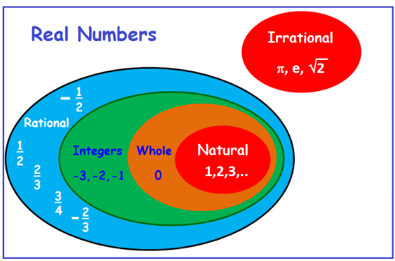
Introduction to Natural Numbers
Non-negative counting numbers excluding zero are called Natural Numbers.
N = 1, 2, 3, 4, 5, ……….
Whole Numbers
All natural numbers including zero are called Whole Numbers.
W = 0, 1, 2, 3, 4, 5, ……………. (Scroll down till end of the page)
Study Tools
Audio, Visual & Digital Content
Integers
All natural numbers, negative numbers and 0, together are called Integers.
Z = – 3, – 2, – 1, 0, 1, 2, 3, 4, …………..
Rational Numbers
The number ‘a’ is called Rational if it can be written in the form of r/s where ‘r’ and ‘s’ are integers and s ≠ 0,
Q = 2/3, 3/5, etc. all are rational numbers.
How to find a rational number between two given numbers?
To find the rational number between two given numbers ‘a’ and ‘b’.

Example:
Find 2 rational numbers between 4 and 5.
Solution:
To find the rational number between 4 and 5
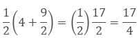
To find another number we will follow the same process again.
Hence the two rational numbers between 4 and 5 are 9/2 and 17/4.
Remark: There could be unlimited rational numbers between any two rational numbers.
Irrational Numbers
The number ‘a’ which cannot be written in the form of p/q is called irrational, where p and q are integers and q ≠ 0 or you can say that the numbers which are not rational are called Irrational Numbers.
Example – √7, √11 etc.
Real Numbers
All numbers including both rational and irrational numbers are called Real Numbers.
R = – 2, – (2/3), 0, 3 and √2
Real Numbers and their Decimal Expansions
1. Rational Numbers
If the rational number is in the form of a/b then by dividing a by b we can get two situations.
a. If the remainder becomes zero
While dividing if we get zero as the remainder after some steps then the decimal expansion of such a number is called terminating.
Example:
7/8 = 0.875
b. If the remainder does not become zero
While dividing if the decimal expansion continues and not becomes zero then it is called non-terminating or repeating expansion.
Example:
1/3 = 0.3333….
Hence, the decimal expansion of rational numbers could be terminating or non-terminating recurring and vice-versa.
2. Irrational Numbers
If we do the decimal expansion of an irrational number then it would be non –terminating non-recurring and vice-versa. i. e. the remainder does not become zero and also not repeated.
Example:
π = 3.141592653589793238……
Representing Real Numbers on the Number Line
To represent the real numbers on the number line we use the process of successive magnification in which we visualise the numbers through a magnifying glass on the number line.
Example:
Step 1: The number lies between 4 and 5, so we divide it into 10 equal parts. Now for the first decimal place, we will mark the number between 4.2 and 4.3.
Step 2: Now we will divide it into 10 equal parts again. The second decimal place will be between 4.26 and 4.27.
Step 3: Now we will again divide it into 10 equal parts. The third decimal place will be between 4.262 and 4.263.
Step 4: By doing the same process again we will mark the point at 4.2626.
Operations on Real Numbers
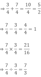
1. The sum, difference, product and quotient of two rational numbers will be rational.
Example:
2. If we add or subtract a rational number with an irrational number then the outcome will be irrational.
Example:
If 5 is a rational number and √7 is an irrational number then 5 + √7 and 5 – √7 are irrational numbers.
3. If we multiply or divide a non-zero rational number with an irrational number then also the outcome will be irrational.
Example:
If 7 is a rational number and √5 is an irrational number then 7√7 and 7/√5 are irrational numbers.
4. The sum, difference, product and quotient of two irrational numbers could be rational or irrational.
Example:
Finding Roots of a Positive Real Number ‘x’ geometrically and mark it on the Number Line
To find √x geometrically
1. First of all, mark the distance x unit from point A on the line so that AB = x unit.
2. From B mark a point C with the distance of 1 unit, so that BC = 1 unit.
3. Take the midpoint of AC and mark it as O. Then take OC as the radius and draw a semicircle.
4. From the point B draw a perpendicular BD which intersects the semicircle at point D.
The length of BD = √x.
To mark the position of √x on the number line, we will take AC as the number line, with B as zero. So C is point 1 on the number line.
Now we will take B as the centre and BD as the radius, and draw the arc on the number line at point E.
Now E is √x on the number line.
Identities Related to Square Roots
If p and q are two positive real numbers
Examples:
1. Simplify

We will use the identity
2. Simplify

We will use the identity
Rationalising the Denominator
Rationalize the denominator means to convert the denominator containing square root term into a rational number by finding the equivalent fraction of the given fraction.
For which we can use the identities of the real numbers.
Example:
Rationalise the denominator of 7/(7- √3).
Solution:
We will use the identity
 here.
here.Laws of Exponents for Real Numbers
If we have a and b as the base and m and n as the exponents, then
1. am × an =am+n
2. (am)n = amn
4. am bm = (ab)m
5. a0 = 1
6. a1 = a
7. 1/an = a-n
- Let a > 0 be a real number and n a positive integer.
- Let a > 0 be a real number. Let m and n be integers such that m and n have no common factors other than 1, and n > 0. Then,
Example:
Simplify the expression (2x3y4) (3xy5)2.
Solution:
Here we will use the law of exponents
am × an =am+n and (am)n = amn
(2x3y4)(3xy5)2
(2x3y4)(3 2 x 2 y10)
18. x3. x2. y4. y10
18. x3+2. y4+10
18x5y14
Hindi Version Key Terms
Topic Terminology
Term
Important Tables
Table:
.
Assessments
Test Your Learning

Advanced Tools For Study Assess Interact The Other Side of Zero | Study
Mind Map Overal Idea Content Speed Notes Quick Coverage Content : (Scroll down till end of the page) Study Tools Audio, Visual & Digital Content Content … Key Terms Topic Terminology Term Important Tables Table: . Assessments Test Your Learning readmore
Mind Map
Overal Idea
Content
Speed Notes
Quick Coverage
Content : (Scroll down till end of the page)
Study Tools
Audio, Visual & Digital Content
Content …
Key Terms
Topic Terminology
Term
Important Tables
Table:
.
Assessments
Test Your Learning
Advanced Tools For Study Assess Interact Visualising Solid Shapes | Study
Mind Map Overal Idea Content Speed Notes Quick Coverage The circle, thesquare, the rectangle, the quadrilateral and the triangle are examples of plane figures; the cube, the cuboid, the sphere, the cylinder, the cone and the pyramid areexamples of solid shapes. (Scroll down till end of the page) Study Tools Audio, Visual & Digital Content… readmore
Mind Map
Overal Idea
Content
Speed Notes
Quick Coverage
The circle, thesquare, the rectangle, the quadrilateral and the triangle are examples of plane figures; the cube, the cuboid, the sphere, the cylinder, the cone and the pyramid areexamples of solid shapes. (Scroll down till end of the page)
Study Tools
Audio, Visual & Digital Content
Plane figures areof two-dimensions (2-D) and the solid shapes are of three- dimensions (3-D). The corners of a solid shape are called its vertices; theline segments ofits skeleton areits edges; and itsflat surfaces areits faces. A net is a skeleton-outline of a solid that can be folded to make it. The same solid can haveseveral types ofnets. Solid shapes can be drawn on a flat surface (like paper) realistically. We call this 2-D representation of a 3-Dsolid. Two types ofsketches of asolid are possible: (a) An oblique sketch does nothave proportional lengths. Still it conveys all important aspects of the appearance of the solid. (b) An isometric sketch is drawn on an isometric dot paper, a sample of which isgiven at theend of thisbook. In an isometric sketch of the solidthe measurements kept proportional. Visualising solidshapesis a veryuseful skill. Youshould be ableto see ‘hidden’ parts of thesolid shape. Different sections of a solid can be viewed in many ways: (a) One way is to viewby cutting or slicing the shape, whichwould result in the cross- section of thesolid. (b) Another way isby observing a 2-D shadow of a 3-Dshape. (c) A third wayis to lookat the shapefrom different angles; the front-view, theside- view and thetop view canprovide a lotof information aboutthe shape observed.
19. When a grouping symbol preceded by ‘ sign is removed or inserted, thenthe sign of eachterm of thecorresponding expression ischanged (from ‘ + ‘ to ‘−’ and from‘− ‘ to + ‘).
Hindi Version Key Terms
Topic Terminology
Term
Important Tables
Table:
.
Assessments
Test Your Learning
Advanced Tools For Study Assess Interact Electric Current | Study
Mind Map Overal Idea Content Speed Notes Quick Coverage Electricity Electricity is a branch of physics that deals with the study of phenomena associated with stationary or moving electric charges. Therefore, the various manifestations of electricity are the result of the accumulation or motion of electrons. Electricity is classified into two types. They are Static… readmore
Mind Map
Overal Idea
Content
Speed Notes
Quick Coverage
Electricity
Electricity is a branch of physics that deals with the study of phenomena associated with stationary or moving electric charges.
Therefore, the various manifestations of electricity are the result of the accumulation or motion of electrons.
Electricity is classified into two types. They are Static Electricity and Current Electricity. (Scroll down to continue …)
Study Tools
Audio, Visual & Digital Content
ELECTRICITY
V-Lab Book Slides V-Class Quiz Solutions Resources of Electricity Static Electricity
Static Electricity is a branch of physics that deals with the study of phenomena associated with stationary electric charges.
Current Electricity.
Current Electricity is a branch of physics that deals with the study of phenomena associated with moving electric charges.
Electric Charge
Electric charge is a fundamental property of matter.
Though we can’t say what is charge with certainty, we can study the properties and behaviour of charge.
Charge is defined as the property associated with matter due to which it produces and experiences electrical and magnetic effects.
The electric charge is caused by the elementary particles, electrons and protons.
Protons possess positive charge, electrons possess negative charge and Neutrons do not possess any charge.
Laws of Electric Charges:
Similar electric charges repel each other
Dissimilar (opposite) electric charges attract each other.
Conductors And Insulators
Conductors are the materials in which electrons move freely.
Example: All metals.
Insulators are the materials which do not have any free electrons to move.
Example: Wood and plastic.
Electric Circuit:
The path of flow of current is known as electric circuit.
Electric Potential Energy
Electric potential energy of a group of charges is defined as the amount of work done in bringing the charges to their respective positions in the system.
Electric Potential At A Point
The electric potential at a point, in an electric field, is defined as the amount of work done in moving a unit + ve charge from infinity to that point, without acceleration or without a change in K.E., against the electric force due to the electric field.
The potential at a point is given by the expression V = W/q
The S.I Unit of potential is mathematically written as 1 volt = 1 joule/1 coulomb.
Potential is a scalar quantity, therefore it is added algebraically.
For a positively charged body, potential is positive and for a negatively charged body potential is negative.
Electric current flows through a conductor only if there is a potential difference across its ends.
Work done in moving a charge in the electric field of another charge is given by:
W = Vq
More is the charge on a body, the more is its potential due to it.
Electric current flows through a conductor only if there is a potential difference across its ends.
Positive charge flows from a body at higher potential to a body at lower potential and negative charge flows from a body at a lower potential to a body at higher potential.
Potential difference
The work done in moving a unit positive charge from one point to another is known as Potential Difference between those points.
Example
The work done in moving a unit positive charge from point A to another point B is known as Potential Difference between the points A and B.
SI Unit: volt
The unit of potential difference is volt (V).
Volt
In other words, Volt is defined as the potential difference between two points, if 1 Joule of work is done in moving 1 coulomb charge from one point to another.
Potential difference between two points across a conductor is measured by using a voltmeter.
Voltmeter is always connected in parallel to the points across which potential difference is to be measured.
Battery:
Battery is an arrangement that creates a constant potential difference between its terminals.
Battery is defined as a combination of a number of cells in series.
Electric Current
The literary meaning of Electric Current is flow of electric charge.
Definition
Electric current is defined as the amount of charge passing a cross section of conductor per a unit time (second in SI Units).
Electric current is expressed mathematically in terms of rate of flow of charges as:
Electric Current =(Net Charge, Q)/(Time,t)
i =n.et , Where n = number of electrons, e = charge of one electron, t= time taken to flow,
Q = charge through the crosssection of the conductor.
The SI unit of electric current is Ampere (A).
- Direction of electric current is the same as the direction of positive charges But it is opposite to the direction of flow of negative charges.
Ohm’s Law
Potential difference, V between two points at a constant temperature is directly proportional to the current, I.
V ∝ I
⇒ V = lR
Where, R is a constant termed as Electric Resistance.
The SI unit of resistance is ohm (Ω)
Q.1. State Ohm’s law. How can it be verified?
Answer: It states “Physical conditions’ remaining same, the current flowing through a conductor is directly proportional to the potential difference across its two ends”.
i.e., V∞ I
or
V = IR, where, R is the constant of proportionality.
R is called the electrical resistance or resistance of the conductor.
Verification:
V∞ I or V = IR, where the constant of proportionality R is called the electrical resistance or resistance of the conductor.
The following circuit diagram is used to verify Ohm’s law.
Take a few cells; connect one cell across a nichrome wire AB, along with an ammeter and a voltmeter as shown in figure. Note the voltage and the current from the voltmeter and the
ammeter.
Now, connect two cells and again note the voltage and the current. Repeat the procedure for three cells and four cells. Calculate the ratio for each set.
You will find the ratio is nearly the same in all cases. If a graph of current against voltage is plotted, it will turn to be a straight line as shown in figure. This shows that the current is directly proportional to the potential difference.
Laws of Electric Resistance
Or
Factors Affecting Resistance
Resistance is directly proportional to length of conductor.
- Resistance is inversely proportional to the area of cross-section.
- Resistance is directly proportional to the temperature.
- Depends on the nature of the material. This is determined by the resistivity of material.
Laws of Electric Resistance
The resistance of any substance depends on the following factors,
Length of the substance.
Cross sectional area of the substance.
The nature of material of the substance.
Temperature of the substance.
There are mainly four (4) laws of resistance from which the resistivity or specific resistance of any substance can easily be determined.
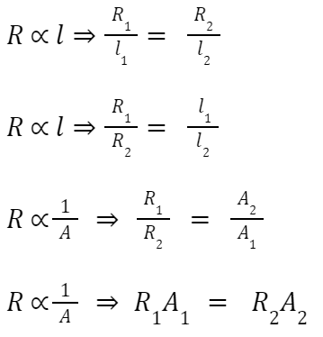
The resistance of a substance is directly proportional to the length of the substance. Electric resistance, R of a substance is written as
Where L is the length of the substance.
The resistance of a substance is inversely proportional to the cross-sectional area of the substance. Electrical resistance R of a substance is

Where A is the cross-sectional area of the substance.
Resistivity
Combining these two laws we get,

Where, ρ (rho) is the proportionality constant and known as resistivity or specific resistance of the material of the conductor or substance.
Now if we put L = 1 and A = 1 in the equation, we get, R = ρ.
That means resistance of a material of unit length having unit cross – sectional area is equal to its resistivity or specific resistance.
Resistivity of a material can alternatively be defined as the electrical resistance between opposite faces of a cube of unit volume of that material.
Unit of Resistivity
The unit of resistivity can be easily determined form its equation
The unit of resistivity is Ω – m in the MKS system and Ω – cm in the CGS system and 1 Ω – m = 100 Ω – cm.
Resistivity
Resistivity is the property of the material. It does depend on the length and area of the conductor.
Resistance = (Resistivity) x (Length of Conductor) / (Cross Sectional Area)
The SI unit of resistivity is ohm-metre.
- Resistivity of metals varies from 10-8 to 10-6.
- Resistivity of insulators varies from 1012 to 1017
- Copper and aluminium are used in electrical transmission due to their low resistivity.
Net Resistance in Resistors In Series
When several resistors are joined in series, the resistance of the combination Rs equals the sum of their individual resistances, R1, R2, R3
It is mathematically expressed as: RS = R1 + R2 + R3
Thus greater than any individual resistance.
Derivation of Net Resistance of Resistors In Series
When two or more resistors are joined in series, then their total resistance is given by the formula:
⇒ RS = R1 + R2 + R3
The current will remain the same through all resistors.
Total voltage is given by: V = V1 + V2 + V3
Voltage across each resistor is given as: V1 = IR1, V2 = IR2, V3 = IR3
⇒ V = V1 + V2 + V3
But Total Voltage V = I × R, Here I = Current in electric circuit and R = Net Resistance in the circuit.
⇒ IR = IR1 + IR2 + IR3 ⇒ IR = I(R1 + R2 + R3) ⇒ R = R1 + R2 + R3
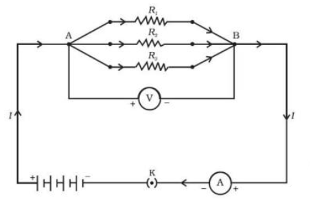
Resistors In Parallel

The reciprocal of the equivalent resistance of a group of resistances joined in parallel is equal to the sum of the reciprocals of the individual resistances.
(V/Rp) = (V/R1) + (V/R2) + (V/R3)
Derivation of Net Resistance of Resistors In Parallel
In this case, voltage is the same across each resistor and is equal to applied voltage.
Total current is given as:
I = I1 + I2 + I3
It is observed that the total current I, is equal to the sum of the separate currents through each branch of the combination.
I = I1 + I2 + I3 ————– (i)
Let Rp be the equivalent resistance of the parallel combination of resistors.
By applying Ohm’s law to the parallel combination of resistors, we have: I = V/Rp ————– (ii)
On applying Ohm’s law to each resistor, we have
I1= V /R1; I2= V /R2; and I3= V /R3 —————– (iii)
From Eqs. (ii) to (iii), we have
(V/Rp) = (V/R1) + (V/R2) + (V/R3)
⇒ V(1/Rp) = V[(1/R1) + (1/R2) + (1/R3)]
⇒ (1/Rp) = [(1/R1) + (1/R2) + (1/R3)] ————– ()
Thus, we may conclude that the reciprocal of the equivalent resistance of a group of resistances joined in parallel is equal to the sum of the reciprocals of the individual resistances.
Advantages of Parallel Combination over Series Combination:
If one component fails in series, then the complete circuit is broken and no component can work properly. Different appliances need different current, this can be met through parallel.
Heating effects of Electric Current
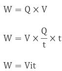
When charge Q moves against the potential difference V in time t, the amount of work is given by-
Joule’s Law of Heating
- Heat produced in a resistor is directly proportional to square root of current.
- It is also directly proportional to resistance for a given current.
- Also, directly proportional to time
⇒ H = l2 Rt
Filament of an electric bulb is made up of tungsten because it has a very high melting point and also does not oxidise readily at a high temperature.
Electric fuse is a safety device to protect the electrical appliance from short circuits.
Electric Power
The rate at which electric energy is dissipated or consumed in an electric current. The SI unit of power is Watt.
⇒ P = Vl
⇒ P = l2 R = V2/R
The commercial unit of electric energy is kilowatt hour (KWh).
Formulae:

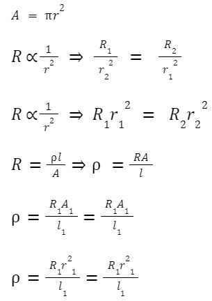
Cylindrical Conductor:

Hindi Version Key Terms
Topic Terminology
Term:
Important Tables
Topic Terminology
Term:
Assessments
Test Your Learning
Advanced Tools For Study Assess Interact Magnetic Effects Of Electric Current | Study
Mind Map Overal Idea Content Speed Notes Quick Coverage Content Study Tools MAGNETIC EFFECTS OF ELECTRIC CURRENT | ELECTROMAGNETISM | FULL NOTES Chapter At A Glance Interactive Notes E-Book L-Plan Solutions Assessment (Quiz Time) Assignment (Worksheet/QB) Summary Interactive Notes Summary L-Plan Q-Bank E-Book Assessment V-Lab Video Key Assignment Magnetic Effects of… readmore
Mind Map
Overal Idea
Content
Speed Notes
Quick Coverage
Content
Study Tools
MAGNETIC EFFECTS OF ELECTRIC CURRENT | ELECTROMAGNETISM | FULL NOTES
Chapter At A Glance
Interactive Notes E-Book L-Plan Solutions Assessment (Quiz Time) Assignment (Worksheet/QB) Summary
Interactive Notes Summary
Magnetic Effects of Electric Current – Electromagnetism
- Electromagnet
- Solenoid
- Electric Motor
Electromagnetic Induction
Electric Effects of Changing Magnetic Fields –
- Electric generators
- Transformer
Electricity and magnetism are linked to each other.
Electric current through conducting wire produces a magnetic field known as electromagnetic induction.
In other words, Generation of magnetic fields due to electric current is known as electromagnetic induction.
Relative motion of a conductor with respect to a magnetic field generates electricity in it.
Magnetic Effects of Electric Current
Accidentally, Oersted discovered that a magnetic field is produced around a current carrying conductor.
Oersted Experiment
Hans Christian Oersted, one of the leading scientists of the 19th
century, played a crucial role in understanding electromagnetism.
In 1820 Oersted accidentally discovered that a compass needle got deflected when an electric current passed through a metallic wire placed nearby.
Through this observation Oersted showed that electricity and magnetism were related phenomena.
His research later created technologies such as the radio, television and fibre optics.
The unit of magnetic field strength is named the Oersted in his honour.
Magnetic Field And Magnetic Lines
The iron filings arrange themselves in a pattern when they are sprinkled around a magnet.
Why do the iron filings arrange in such a pattern?
What does this pattern demonstrate?
The iron filings experience a magnetic force in its surroundings due to the magnetic field.
The force makes iron filings to arrange in a pattern.
The region surrounding a magnet, in which the force of the magnet can be detected, is known as a magnetic field.
The lines along which the iron filings align themselves represent the lines of magnetic field or magnetic field lines.
Are there other ways of obtaining magnetic field lines around a bar magnet?
Yes, we can draw the field lines of a bar magnet using a magnetic compass.
Magnetic Compass
- Magnetic compass is a device used to find the Geographic south and north direction.
- Compass needle gets deflected when brought near a magnet.
- The ends of the compass needle point approximately towards Geographic north and south directions.
- The end pointing towards Geographic north is called the north seeking pole or north pole.
- The other end that points towards south is called south seeking pole or south pole.
- Like magnetic poles repel, while unlike magnetic poles attract each other.
Magnetic field
A magnetic field exists in the region surrounding a magnet, in which the force of the magnet can be detected.
The region surrounding a magnet, in which the force of the magnet can be detected, is said to have a magnetic field.
Magnetic field has both direction and magnitude. Therefore the magnetic field is a vector quantity.
The direction of the magnetic field is taken to be the direction in which the north pole of the compass needle moves inside it.
Therefore it is taken by convention that the field lines emerge from the north pole and merge at the south pole.
Inside the magnet, the direction of field lines is from its south pole to its
north pole.
Thus the magnetic field lines are closed curves.
The relative strength of the magnetic field is shown by the degree of
closeness of the field lines.
The field is stronger, that is, the force acting on the pole of another magnet placed is greater where the field lines are crowded.
No two field-lines are found to cross each other.
If they did, it would mean that at the point of intersection, the compass needle would point towards two directions, which is not possible.
Magnetic Field lines
- A magnetic field line is the path along which a hypothetical free north pole would tend to move.
- Field lines are used to represent a magnetic field.
- The direction of the magnetic field at a point is given by the direction that a north pole placed at that point would take.
- Field lines are shown closer together where the magnetic field is greater.
MAGNETIC FIELD DUE TO A CURRENT-CARRYING CONDUCTOR
A conductor carrying an electric current has a magnetic field associated with it.
The pattern of the magnetic field around a conductor due to an electric current flowing through it depends on the shape of the conductor.
- Straight Current Carrying Conductor
- Circular loop
- Coil
- Electromagnetic Induction By A Coil
- Solenoid
- Electromagnet
MAGNETIC FIELD DUE TO A STRAIGHT CURRENT-CARRYING
CONDUCTOR
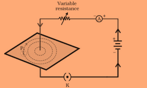
Take a battery (12 V), a variable resistance (or a rheostat), an ammeter (0–5 A), a plug key, connecting wires and a long straight thick copper wire.
Insert the thick wire through the centre, normal to the plane of a rectangular cardboard.
Take care that the cardboard is fixed and does not slide up or down.
Connect the copper wire vertically between thepoints X and Y, as shown in Fig. 13.6 (a), in series with the battery, a plug and key.
Sprinkle some iron filings uniformly on the cardboard. (You may use a salt sprinkler for this purpose.)
Keep the variable of the rheostat at a fixed position and note the current through the ammeter.
Close the key so that a current flows through the wire. Ensure that the copper wire placed between the points X and Y remains vertically
straight.
Gently tap the cardboard a few times. Observe The pattern of the iron filings. You would find that the iron filings align themselves showing a pattern of concentric circles around the copper wire.
What do these concentric circles represent?
They represent the magnetic field lines.
How can the direction of the magnetic field be found? Place a compass at a point (say P) over a circle.
Observe the direction of the needle.
The direction of the north pole of the compass needle would give the direction of the field lines produced by the electric current through the straight wire at point P. Show the direction by an arrow.
Does the direction of magnetic field lines get reversed if the direction of current through the straight copper wire is reversed? Check it out.
Finding Direction of Magnetic Field
Right Hand Thumb Rule Or Right Hand Grip Rule
Imagine that you are holding a current-carrying straight conductor in your right hand such that the thumb points towards the direction of current.
Then your fingers will wrap around the conductor in the direction of the field lines of the magnetic field, as shown in Figure known as the right-hand thumb rule*.
The field lines about the wire consist of a series of concentric circles whose direction is given by the right-hand rule.
Right Hand Thumb Rule
Right hand thumb rule states that if we hold the conductor in the right hand such that the thumb points in the direction of electric current, then the direction in which the fingers curl gives the direction of the magnetic field
If we point the thumb downwards in the direction of the current, the magnetic field would be represented by the curled fingers as the circles around the conductor.
So, if it is viewed from the above plane these field lines will be clockwise circles, but the direction of the magnetic field at any point on these circular magnetic lines is in the direction of the tangent drawn to the circular magnetic lines at the desired points.
Example:
A current through a horizontal power line flows in an east to west direction. What is the direction of the magnetic field at a point directly below it and at a point directly above it?
Solution
The current is in the east-west direction. Applying the right-hand thumb rule, we get that the magnetic field (at any point below or above the wire) turns clockwise in a plane perpendicular to the wire, when viewed from the east end, and anti-clockwise, when viewed from the west end.
Maxwell’s Cork-Screw Rule:
Maxwell’ cork screw rule is also known as maxwell’s right hand thumb rule Maxwell’s right hand thumb rule states that, if the head of a cork-Screw is rotated such that the tip of the screw advances in the direction of electric current, then the direction of rotation of the head of the screw represents the direction of the magnetic field around the conductor.
A magnetic field caused by a current-carrying conductor consists of sets of concentric lines of force. The direction of the magnetic field lines depends on the direction of the current passed through the conductor.
Example 13.1
A current through a horizontal power line flows in east to west
direction. What is the direction of magnetic field at a point directly
below it and at a point directly above it?
Solution
The current is in the east-west direction. Applying the right-hand
thumb rule, we get that the magnetic field (at any point below or
above the wire) turns clockwise in a plane perpendicular to the wire,
when viewed from the east end, and anti-clockwise, when viewed
from the west end.
Clock-S Rule
Clock-S rule is a rule which helps us to find the formation of magnetic South Pole due to electromagnetic induction in a current carrying conducting coil.
According to clocks rule if one face of a current carrying conducting coil is placed such that one face of the coil is faced to us and current is moving in the clockwise direction with respect to us then the face of the coil which is faced to us becomes as a magnetic south pole and the other face behaves as the north magnetic pole.
A current carrying conductor in the form of a rectangular loop behaves like a magnet and when suspended in an external magnetic field experiences force.
*SNOW Rule
Case 1
The SNOW rule states that if the current is flowing in an electric circuit from South to North direction and a magnetic compass is placed Over the conducting wire, the needle of the compass deflects in the direction of west.
Case 2
The SNOW rule states that if the current is flowing in an electric circuit from North to South direction and a magnetic compass is placed Over the conducting wire, the needle of the compass deflects in the direction of east.
Case 3
The SNOW rule states that if the current is flowing in an electric circuit from South to North direction and a magnetic compass is placed Below the conducting wire, the needle of the compass deflects in the direction of east.
Case 4
The SNOW rule states that if the current is flowing in an electric circuit from North to South direction and a magnetic compass is placed Above the conducting wire, the needle of the compass deflects in the direction of west.
The SNOW rule states that if the current is flowing in an electric circuit from North to South direction and a magnetic compass is placed Below the conducting wire, the needle of the compass deflects in the direction of east.
Current Direction Compass Position N – of Compass Deflection S – of Compass Deflection South to North Above SNOWWest East North to South Above East West South to North Below East West North to South Below West East Magnetic Field due to a Current through a
Circular Loop

We have so far observed the pattern of the magnetic field lines produced around a current-carrying straight wire.
Suppose this straight wire is bent in the form of a circular loop and a current is passed through it.
What would the magnetic field lines look like?
We know that the magnetic field produced by a current-carrying straight wire depends inversely on the distance from it.
Similarly at every point of a current-carrying circular loop, the concentric circles representing the magnetic field around it would become larger and larger as we move away from the wire (Fig. 13.8). By the time we reach the centre of the circular loop, the arcs of these big circles would appear as straight lines.
Every point on the wire carrying current would give rise to the magnetic field appearing as straight lines at the centre of the loop.
By applying the right hand rule, it is easy to check that every section of the wire contributes to the magnetic field lines in the same direction
within the loop.
We know that the magnetic field produced by a current-carrying
wire at a given point depends directly on the current passing through it.
Therefore, if there is a circular coil having n turns, the field produced is
n times as large as that produced by a single turn.
This is because the current in each circular turn has the same direction, and the field due to each turn then just adds up.
Factors affecting magnetic field of a circular current carrying conductor-
- Magnetic field is directly proportional to the current passing through the conductor.
- Magnetic field is inversely proportional to the distance from the conductor.
- Magnetic field is directly proportional to number of turns in coil.
Solenoid
The solenoid is an electromagnet which is a long cylindrical coil of wire consisting of a large number of turns bound together very tightly.
Note: The length of the coil should be longer than its diameter. (Or)
Solenoid is a coil of a number of turns of insulated copper wire closely wrapped in the shape of a cylinder.
When a soft iron rod is placed inside the solenoid, it behaves like an electromagnet.
The use of soft iron as core in the solenoid produces the strongest magnetism.
A solenoid consists of an insulated conducting wire wound on a cylindrical tube made of plastic or cardboard.
Magnetic Field due to a Current in a Solenoid
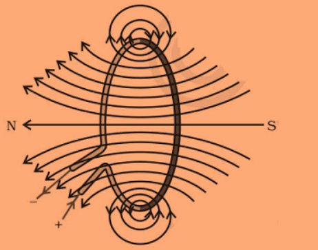
The magnetic field of a solenoid carrying a current is similar to that of a bar magnet.
Compare the pattern of the field with the magnetic field around a bar magnet.
Do they look similar?
Yes, they are similar.
In fact, one end of the solenoid behaves as a magnetic north pole, while the other behaves as the south pole.
The field lines inside the solenoid are in the form of parallel straight lines.
This indicates that the magnetic field is the same at all points inside the solenoid.
That is, the field is uniform inside the solenoid.
These appear to be similar to that of a bar magnet.
One end of the solenoid behaves like the North Pole and the other end behaves like the South Pole.
Magnetic field lines inside the solenoid are in the form of parallel straight lines.
This means that the field is the same at all the points inside the solenoid.
Electromagnet
An electromagnet consists of a core of soft iron wrapped around with a coil of insulated copper wire.
An electromagnet is a magnet made up of a coil of insulated wire wrapped around a soft iron core that is magnetised only when current flows through the wire.
A strong magnetic field produced inside a solenoid can be used to magnetise a piece of magnetic material, like soft iron, when placed inside the coil.
It is a temporary magnet that can be easily demagnetized.
In this type of magnet, polarity can be reversed and strength can be varied. They are very strong magnets.
Magnetic Field of An electromagnet
Force on A current-carrying conductor placed in a magnetic field
Placing a current-carrying conductor in a magnetic field experiences a force.
Finding direction of force on a current-carrying conductor placed in a magnetic field Using Fleming’s left-hand rule
If the direction of the magnetic field and that of the current are mutually perpendicular to each other, then the force acting on the conductor will be perpendicular to both and will be given by Fleming’s left-hand rule.
Flemings Left Hand Rule
Stretch the thumb, forefinger and middle finger of the left hand such that they are mutually perpendicular. If the forefinger is in the direction of the magnetic field, Central finger in the direction of current, then the thumb will point in the direction of motion or force.
Rules & Laws of Electromagnetism
Clock-S Rule
Clock-S rule is a rule which helps us to find the formation of magnetic South Pole due to electromagnetic induction in a current carrying conducting coil.
According to clocks rule if one face of a current carrying conducting coil is placed such that one face of the coil is faced to us and current is moving in the clockwise direction with respect to us then the face of the coil which is faced to us becomes as a magnetic south pole and the other face behaves as the north magnetic pole.
A current carrying conductor in the form of a rectangular loop behaves like a magnet and when suspended in an external magnetic field experiences force.
SNOW Rule
Case 1
The SNOW rule states that if the current is flowing in an electric circuit from South to North direction and a magnetic compass is placed Over the conducting wire, the needle of the compass deflects in the direction of west.
Case 2
The SNOW rule states that if the current is flowing in an electric circuit from North to South direction and a magnetic compass is placed Over the conducting wire, the needle of the compass deflects in the direction of east.
Case 3
The SNOW rule states that if the current is flowing in an electric circuit from South to North direction and a magnetic compass is placed Below the conducting wire, the needle of the compass deflects in the direction of east.
Case 2
The SNOW rule states that if the current is flowing in an electric circuit from North to South direction and a magnetic compass is placed Below the conducting wire, the needle of the compass deflects in the direction of west.
Current Direction Compass Position N – of Compass Deflection South to North Above SNOWWest North to South Above East South to North Below East North to South Below West Maxwell’s cork-screw rule:
Maxwell’ cork screw rule is also known as maxwell’s right hand thumb ruleIf the head of a cork-Screw is rotated such that the tip of the screw advances in the direction of electric current, then the direction of rotation of the head of the screw represents the direction of the magnetic field around the conductor.
A magnetic field caused by a current-carrying conductor consists of sets of concentric lines of force. The direction of the magnetic field lines depends on the direction of the current passed through the conductor.
Ampere Right Hand Thumb Rule
Right hand thumb rule states that if we hold the conductor in the right hand such that the thumb points in the direction of electric current, then the direction in which the fingers curl gives the direction of the magnetic field
If we point the thumb downwards in the direction of the current, the magnetic field would be represented by the curled fingers as the circles around the conductor.
So, if it is viewed from the above plane this field lines will be clockwise circles, but the direction of the magnetic field at any point on this circular magnetic lines is in the direction of the tangent drawn to the circular magnetic lines at the desired points.
Example 13.1
A current through a horizontal power line flows in east to west
direction. What is the direction of magnetic field at a point directly
below it and at a point directly above it?
Solution
The current is in the east-west direction. Applying the right-hand
thumb rule, we get that the magnetic field (at any point below or
above the wire) turns clockwise in a plane perpendicular to the wire,
when viewed from the east end, and anti-clockwise, when viewed
from the west end.
Fleming’s Right Hand rule (Working Principle of Transformer and generator )
Fleming’s right hand rule gives the direction of the induced current in a conductor when it is moved in a magnetic field.
Transformers are based on this principle, which consist of a primary coil and a secondary coil.
The number of turns in the coils is selected based on the type of the transformer to be made, namely, step-up or step-down.
Magnetic Field Due to An Electric Conducting Coil (Motor Working Basics)
Electric Motor
Electric Motor
An electric motor is a device that converts electrical energy into mechanical energy.
Fleming’s left-hand rule is the basis of an electric motor.
A rotating device that converts electrical energy to mechanical energy.
Working Principle: The Working Principle of Electric motor is Fleming’s Left Hand Rule.
Construction of Electric Motor:
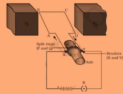
It consists of a rectangular coil ABCD made up of insulated copper wire.
The coil is placed perpendicular to the magnetic field.
There are two conducting brushes X and Y.
Current in coil ABCD enters through a source battery through conducting brush X and flows back to the battery through brush Y.
The split ring acts as a commutator.
It reverses the direction of flow of current in a commutator.
They are used in electromagnets, as soft iron core on which coil is wound.
Armature enhances the power of the motor.
Electric Motor

Working Principle
Working Principle of electric motors is Fleming’s left hand rule.
The direction of the force is given by Fleming’s left hand rule. This gives the basis for an electric motor.
An electric motor essentially consists of a coil as an armature, a split ring commutator for changing the direction of the current in the coil.
There are two brushes linked with the split rings that maintain the contact with the armature for the current flow.
Electric motor converts electrical energy to mechanical energy.
A number of such loops form a coil and the coil is termed solenoid.
If there is a soft iron core in the solenoid, it behaves like a magnet as long as there is current through the coil. Thus it is an electromagnet.
When an electric current passes through a conductor, a magnetic field is created around the conductor. This phenomenon is known as the magnetic effect of electricity.
A magnetic field is the extent of space surrounding a magnet where the magnet’s effect can be felt.
Magnetic field lines represent the lines of action of the force acting on a unit North Pole placed in a magnetic field.
Electromagnetic Induction
Electromagnetic Induction – Electric Effects of Changing Magnetic Field
The phenomenon of electromagnetic induction is the production of induced current in a coil placed in a region where the magnetic field changes with time.
The magnetic field may change due to a relative motion between the coil and a magnet placed near to the coil.
If the coil is placed near to a current-carrying conductor, the
the magnetic field may change either due to a change in the current through the conductor or due to the relative motion between the coil and conductor.
The direction of the induced current is given by the Fleming’s right-hand rule.
Fleming’s Right Hand Rule
A generator converts mechanical energy into electrical energy. It works on the basis of electromagnetic induction.
Electromagnetic Induction is the electric effects of relative motion between magnetic field and electric conductor.
When we place a conductor in a changing magnetic field, some current is induced in it. This current is known as Induced Current and the phenomenon is known as Electromagnetic Induction.
Faraday’s Experiment
The working principle of electric generators and Transformers is Fleming’s right hand rule.
Faraday’s experiment proved that the strength of the induced current depends on several factors like the strength of the magnet, the speed of motion of the magnet, its orientation, the number of turns in the coil and the diameter of the coil. The induced current can be detected by a galvanometer.
Electric Generator
An electric device that converts mechanical energy into electrical energy is called an electric generator.
Working Principle: Fleming Right Hand Rule
Fleming Right Hand Rule
Hold the forefinger, middle finger and thumb of your right hand at right angles to each other. Forefinger points towards the direction of the magnetic field, thumb points in the direction of motion of conductor and middle finger shows direction of induced current.
Electric Energy is a device used to convert mechanical energy into an alternating form of electrical energy. It consists of insulated copper wire, magnetic poles, split rings, axle, brushes and galvanometer.
The axle is rotated so that it moves clockwise, that is AB moves up and CD moves down. After half rotation, CD starts to move up and AB moves down. After every half rotation current changes its direction, this is called AC current.
Electric generators work on the same principle.
They have an armature which is free to rotate in a magnetic field.
Its terminals are connected to two slip rings, which are further connected to two brushes and they are connected across a load resistance through which the generated electricity can be trapped.
The rotation of the armature in the magnetic field changes the magnetic flux in the coil of the armature and an electric current is induced.
As the direction of the induced current changes for every half rotation, it is called alternating current.
The current at the power plants is distributed through transmission lines at a high voltage and hence the lines are referred to as high tension power lines.
At the substations these are stepped down to a lower voltage and supplied to houses at a low voltage.
A domestic electric circuit essentially contains mains, a fuse, live or line, neutral and earth wires.
From the poles supply cables bring the current to the mains.
Within the house, all the equipment is connected in parallel.
Electromagnetic induction (EMI) is the process of generating an electromotive force by moving a conductor through a magnetic field.
The electromotive force generated due to electromagnetic induction is called induced emf. The current due to induced emf is called induced current.
Alternating current (AC) is the current induced by an AC generator. AC current changes direction periodically. Direct current (DC) always flows in one direction, but its voltage may increase or decrease.
An electric motor is different from an electric generator. A generator converts mechanical energy (Kinetic energy) into electrical energy while an electric motor converts electrical energy into mechanical energy (Kinetic energy).
AC Generator:
Principle: It works on the principle that when a coil rotates in a uniform magnetic field, a current is induced in the coil. The direction of induced current is determined by Fleming’s right hand rule.
Construction: An ac generator consists of the following components as shown in figure.
(i) Armature coil: It consists of a large number of turns of a rectangular coil ABCD made of copper wire wound over a soft iron laminated core.
(ii) Strong field magnets: Two concave poles (NS) of permanent magnets between which the armature coil is rotated.
(iii) Slip-rings: The two ends of the coil are welded to two different circular metallic rings R, and R,. These rings are called the slip-rings. The function of the slip-rings is to ensure that the ion of current flowing through the coil after each half rotation.
A schematic diagram of common domestic circuit is as shown below
(iv) Brushes : Two carbon brushes B, and B2 make a contact with the slip-rings R, and R2
An electric generator is as shown in fig. 7.7.
Domestic Electric Circuit
HouseHold Electric Circuits
In our houses we receive AC electric power of 220 V with a frequency of 50 Hz. One of the wires in this supply is with red insulation, called live wire.
The other one is of black insulation, which is a neutral wire. The potential difference between the two is 220 V.
The third is the earth wire that has green insulation and this is connected
to a metallic body deep inside earth. It is used as a safety measure to ensure that any leakage of current to a metallic body does not give any severe shock to a user.
Fuse is the most important safety device, used for protecting the circuits due to short-circuiting or overloading of the circuits.
Electrical components and wires fitted in a household to supply electricity to various appliances form a domestic electric circuit.
The old colour convention of the three wires used in household electrical circuits was Red, called live wire, Black, called neutral wire and Green, called earth wire. Now, this colour convention has changed.
The new colour convention is Brown, called live wire, Light blue, called neutral wire and Green or Yellow, called earth wire.
In our houses, we receive AC electric power of 220 V with a frequency of 50 Hz. One of the wires in this supply is with red insulation, called live wire.
The other one is of black insulation, which is a neutral wire. The potential difference between the two is 220 V.
The third is the earth wire that has green insulation and this is connected to a metallic body deep inside earth.
It is used as a safety measure to ensure that any leakage of current to a metallic body does not give any severe shock to a user.
Earthing
Earthing of an electrical appliance is very important.
Suppose, a conductor is exposed to the appliance due to bad insulation.
If a person touches such an appliance, he will receive a severe shock.
If the metal casing of the appliance is connected to the earth with the help of a conductor, the metal casing will be then at the same potential as the earth i.e., zero volt.
If there is a leakage of current, the current will safely flow to the earth.
The earth connection can also save the appliance from the damage.
Fuse
Fuse is the most important safety device, used for protecting the circuits due to short-circuiting or overloading of the circuits.
It is a safety device to limit the current in an electric circuit.
It prevents the electric appliances from damage.
It is made up of material which has high resistivity and low melting point.
Exam Revision
Magnetic Compass
A compass needle is a small magnet. Its one end, which points towards north, is called a north pole, and the other end, which points towards south, is called a south pole.
Magnetic Field
A magnetic field exists in the region surrounding a magnet, in which the force of the magnet can be detected.
Field lines
Field lines are used to represent a magnetic field. A field line is the path along which a hypothetical free north pole would tend to move. The direction of the magnetic field at a point is given by the direction that a north pole placed at that point would take. Field lines are shown closer together where the magnetic field is greater.
Magnetic Effects of Electric Current
A metallic wire carrying an electric current has a magnetic field associated with it.
The field lines about the wire consist of a series of concentric circles whose direction is given by the right-hand rule.
Right Hand Rule
Magnetic Field Around a Conductor Due to An Electric Current
The pattern of the magnetic field around a conductor due to an electric current flowing through it depends on the shape of the conductor.
Magnetic Field of a solenoid
The magnetic field of a solenoid carrying a current is similar to that of a bar magnet.
Magnetic Field of An electromagnet
An electromagnet consists of a core of soft iron wrapped around with a coil of insulated copper wire.
Force on A current-carrying conductor placed in a magnetic field
O placing a current-carrying conductor in a magnetic field experiences a force.
Direction of Force on A current-carrying conductor placed in a magnetic field Using Fleming’s left-hand rule
If the direction of the magnetic field and that of the current are mutually perpendicular to each other, then the force acting on the conductor will be perpendicular to both and will be given by Fleming’s left-hand rule.
Electric Motor
An electric motor is a device that converts electric energy into mechanical energy.
Fleming’s left-hand rule is the basis of an electric motor.
Electromagnetic Induction – Electric Effects of Changing Magnetic Field
The phenomenon of electromagnetic induction is the production of induced current in a coil placed in a region where the magnetic field changes with time.
The magnetic field may change due to a relative motion between the coil and a magnet placed near to the coil.
If the coil is placed near to a current-carrying conductor, the
magnetic field may change either due to a change in the current through the conductor or due to the relative motion between the coil and conductor.
The direction of the induced current is given by the Fleming’s right-hand rule.
Fleming’s Right Hand Rule
A generator converts mechanical energy into electrical energy. It works on the basis of electromagnetic induction.
HouseHold Electric Circuits
In our houses we receive AC electric power of 220 V with a frequency of 50 Hz. One of the wires in this supply is with red insulation, called live wire.
The other one is of black insulation, which is a neutral wire. The potential difference between the two is 220 V.
The third is the earth wire that has green insulation and this is connected
to a metallic body deep inside earth. It is used as a safety measure to ensure that any leakage of current to a metallic body does not give any severe shock to a user.
Fuse is the most important safety device, used for protecting the circuits due to short-circuiting or overloading of the circuits.
Key Terms
Topic Terminology
Term:
Important Tables
Topic Terminology
Term:
Assessments
Test Your Learning
Advanced Tools For Study Assess Interact










 here.
here.